Showing posts with label WiFi. Show all posts

Wednesday, September 17, 2025

QRCode Clock with ESP32C3 Dev Module

-----
Nothing is more frustrating than needing the time and not having a watch, but watches can be expensive and boring so we programed this ~$2.00 USD ESP32C3 Dev Module with on-board OLED to provide the time in a low cost and interesting way.

 Oh, to make it work you also need a smart phone.... 

-----

After uploading the source code below you will get a QRCode on the OLED that conveniently provides a second by second account of the time which you can read from your smart phone camera.  Here's the demo:


This timekeeping device is cheap and extremely accurate.  
-----

// QRCode Clock
// QRCode on OLED is updated each second 
// time the time of day as HH:MM:SS in 24 hr format.
//
// Board (~$4) is ESP32C3 Dev Module with onboard OLED.
// 
// Details at: https://www.whiskeytangohotel.com/
// SEPT 2025


#include <Arduino.h>
#include <U8g2lib.h>
#include <Wire.h>
#include <WiFi.h>
#include "time.h"
#include "QRCodeGenerator.h"

// WiFi credentials
const char* ssid     = "YOURSSID";
const char* password = "YOURWIFIPASSWORD";
const char* ntpServer = "pool.ntp.org";

// A few Google searches led me to this:
U8G2_SSD1306_72X40_ER_F_HW_I2C u8g2(U8G2_R0, U8X8_PIN_NONE);

void setup() {
  Wire.begin(5, 6);         // I2C 
  Wire.setClock(100000);    // slow for stability
  delay(200);               // power-up delay
  u8g2.begin();

  // Connecting WiFi status screen
  u8g2.clearBuffer();
  u8g2.setFont(u8g2_font_6x10_tr);
  u8g2.drawStr(0, 15, "Connecting...");
  u8g2.sendBuffer();

  WiFi.begin(ssid, password);
  while (WiFi.status() != WL_CONNECTED) {
    delay(500);
  }

  configTzTime("CST6CDT,M3.2.0/2,M11.1.0/2", ntpServer); //Central Time
}

void loop() {
  struct tm timeinfo;
  if (!getLocalTime(&timeinfo)) {
    delay(2000);
    return;
  }

  // Format time string (HH:MM:SS) 24 hour time
  char timeStr[16];
  strftime(timeStr, sizeof(timeStr), "%H:%M:%S", &timeinfo);

  // Generate QR code
  QRCode qrcode;
  const uint8_t qrVersion = 3;  // 29x29 QRCode
  uint8_t qrcodeData[qrcode_getBufferSize(qrVersion)];
  qrcode_initText(&qrcode, qrcodeData, qrVersion, 0, timeStr);

  // Scale/Center QRCode to fit 64x32 OLED but remember QRCodes are square
  int scale = 1;  // keep modules square
  int width = qrcode.size * scale;
  int height = qrcode.size * scale;
  int xOffset = (64 - width) / 2;
  int yOffset = (32 - height) / 2;

  // Draw QRCode to OLED
  u8g2.clearBuffer();
  for (uint8_t y = 0; y < qrcode.size; y++) {
    for (uint8_t x = 0; x < qrcode.size; x++) {
      if (qrcode_getModule(&qrcode, x, y)) {
        u8g2.drawBox(xOffset + x * scale, yOffset + y * scale, scale, scale);
      }
    }
  }
  u8g2.sendBuffer();

  delay(1000);  // refresh once per second
}

-----


Saturday, July 30, 2022

@Cheerlights Project: Now with Sound

-----

We did a @cheerlights project that used a Raspberry PI Zero and a Blinkt! LED bar to keep track of the last eight color changes the cheerlights server received.  We put the rig in the garage and enjoyed the Blinkt! LED bar change color as The Internet masses dictated what rainbow of colors would be displayed.  But, that wasn't enough.  To control CheerLights, send a tweet to @cheerlights or include “cheerlights” somewhere in your message with the name of a color. for example, @CheerLights Paint the town red. [UPDATE: After The RocketMan took over Twitter the API no longer functions.  To learn more about how to control any cheerlights project, including this one, go to https://cheerlights.com/]

-----

The Amazon impulse buy AI suggested that our life could be complete only if we spent $7.99US on the DollaTEK DY-SV17F mini MP3 module and an idea was born.  What if, we added sound to the existing @cheerlights project and a short MP3 sound clip was played in addition to the LED color change?   If The Internet masses demand 'purple' we change an LED to 'purple' and play a clip from the song "Purple Rain".   'pink' would trigger "Pink Cadillac".  'red' triggers "Red Red Wine".  You get the idea....

-----

The DollaTEK DY-SV17F module has a UART mode to reduce the pins needed to control it, but the module is big on features and short on documentation for use with the Raspberry PI.   After not being able to get UART mode to work (probably user error) it was decided to use the plentiful GPIO pins on the Raspberry PI Zero and go with a parallel interface solution.   Here is a short video of the result: 

----- 

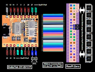
Connection was straightforward:


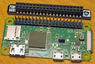
 The rig looked like this on the bench:

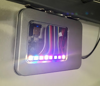
Packaged and mounted in the garage:

 
-----

For the rig to work the two python programs below run on the RasPI at the same time; cheerlights.py and cheerlights_sound.py.

-----

The cheerlights.py source code below updates the LEDs on the Blinkt! LED bar:

 #!/usr/bin/env python

# Cheerlights with Pimoroni BlinkT module and RasPI Zero
#
# A tweet to @Cheerlights will change the LEFT most color of the BlinkT (LED#7)
# Color history maintained by shifting old color to the RIGHT (LED#0)

# Valid color tweets to @Cheerlights are:
# RED GREEN BLUE CYAN WHITE OLDLACE PURPLE MAGENTA YELLOW ORANGE PINK
#
# Project details at:
# WhiskeyTangoHotel.Com
#
# MARCH 2022
# JULY 2022 add DollaTek DY-SV17F to play sound clip pwr color as independent and seperate program
#

import time
import sys

try:
    import requests  #  needed to poll @Cheerlights
except ImportError:
    exit("Install needed to run. Use the command: sudo pip install requests")

from blinkt import set_clear_on_exit, set_pixel, show, set_brightness, clear # https://shop.pimoroni.com/products/blinkt#

LED_delay = 0.5
brightness = 0.1 # 0.05 is lowest useable dim.  1.0 is full bright (the BLINKT is *really* bright if you want!)

#Set up a matrix for r, g, b values (m stands for matrix)
rm = [0,1,2,3,4,5,6,7,8]
gm = [0,1,2,3,4,5,6,7,8]
bm = [0,1,2,3,4,5,6,7,8]

# set_pixel(pixel_no, red, green, blue, brightness)

print "Testing LEDs..."
print "---------------------------------------------"
for i in range(3):
    for j in range (0,8):
        set_pixel(j, 30, 0, 0, brightness)
    print "RED"
    show()
    time.sleep(LED_delay)
    for j in range (0,8):
        set_pixel(j, 0, 30, 0, brightness)
    print "GREEN"
    show()
    time.sleep(LED_delay)
    for j in range (0,8):
        set_pixel(j, 0, 0, 30, brightness)
    print "BLUE"
    show()
    time.sleep(LED_delay)

    # all LEDs off
    for j in range (0,8):
        set_pixel(j, 0, 0,0)
    show()
print "LED Self test complete!"

for j in range (0,8): # set values that we know are 'wrong' to enter main loop
    rm[j] = 73.73
    gm[j] = 73.73
    bm[j] = 73.73
print " "

while True:
    try:
        r = requests.get('http://api.thingspeak.com/channels/1417/field/2/last.json')
        col = r.json()['field2']
        r, g, b = tuple(ord(c) for c in col[1:].lower().decode('hex'))
        time.sleep(5)  # delay until we look for a new color change


        if (r != rm[7]) or (g != gm[7]) or (b != bm[7]):  # new color selected
            print "New color placed far LEFT.  Shift old colors RIGHT one place"
            for j in range (0,7): #shift in the new values
                rm[j] = rm[j+1]
                gm[j] = gm[j+1]
                bm[j] = bm[j+1]               
                set_pixel(j, rm[j], gm[j], bm[j], brightness)
                show()
                time.sleep(LED_delay) # show change as a sweep

            rm[7] = r
            gm[7] = g
            bm[7] = b
            set_pixel(7, rm[7], gm[7], bm[7], brightness)
            show()
    
    # All LED off on control C
    except KeyboardInterrupt:
        print("stopping ...")
        sys.exit(0)
    except:
        time.sleep(1)
-----

The cheerlights_sound.py source code below runs the DollaTEK DY-SV17F:


# Cheerlights with DY-SV17F module for sound and RasPI Zero
#
# A tweet to @Cheerlights will play sound file

# Valid color tweets to @Cheerlights are:
# RED GREEN BLUE CYAN WHITE OLDLACE PURPLE MAGENTA YELLOW ORANGE PINK
#
# Project details at:
# WhiskeyTangoHotel.Com
#
# MARCH 2022
# JULY 2022 add DollaTek DY-SV17F to play sound clip pwr color as independent and seperate program
#

# DallaTEK DY-SV17F Files mapped to Cheerlights color.  MP3s vary from ~10-30 secs
# 00001.mp3 = red (red red wine)
# 00002.mp3 = green (green green gras of home)
# 00003.mp3 = blue (blue bayoe)
# 00004.mp3 = cyan (call me cyan)
# 00005.mp3 = white (whiter shade of pale)
# 00006.mp3 = oldlace (leather and lace)
# 00007.mp3 = purple (purple rain [of course])
# 00008.mp3 - magenta (some song calll 'magenta')
# 00009.mp3 = yellow (yellow submarine)
# 00010.mp3 = orange (orange crush)
# 00011.mp3 = pink (pink cadi)
# 00012.mp3 = start speaker test file (start me up)

import time
import requests  #  needed to poll @Cheerlights

import RPi.GPIO as GPIO
GPIO.setmode(GPIO.BOARD) # to use Raspberry PI board pin numbers

#Define some pins and vars
IO_0 = 31
IO_1 = 29
IO_2 = 3
IO_3 = 5
IO_4 = 7
IO_5 = 11
IO_6 = 13
IO_7 = 15

CON_1 = 19
CON_2 = 21
CON_3 = 23

current_color_mp3 = "clear" # set color value that we know is 'wrong' to enter main loop
delta_time = 0 # track seconds since last color change

#Setup the GPIO and make sure the speaker is OFF

GPIO.setwarnings(False)  # To disable warnings.
GPIO.setup(IO_0, GPIO.OUT)
GPIO.setup(IO_1, GPIO.OUT)
GPIO.setup(IO_2, GPIO.OUT)
GPIO.setup(IO_3, GPIO.OUT)
GPIO.setup(IO_4, GPIO.OUT)
GPIO.setup(IO_5, GPIO.OUT)
GPIO.setup(IO_6, GPIO.OUT)
GPIO.setup(IO_7, GPIO.OUT)

GPIO.setup(CON_1, GPIO.OUT)
GPIO.setup(CON_2, GPIO.OUT)
GPIO.setup(CON_3, GPIO.OUT)   #HIGH = speaker sound.  LOW = sound off

GPIO.output(CON_1, GPIO.LOW)
GPIO.output(CON_2, GPIO.LOW)
GPIO.output(CON_3, GPIO.LOW) #HIGH = speaker sound.  LOW = sound off

# Test the speaker at startup
print "Testing speaker..."
GPIO.output(CON_3, GPIO.HIGH) # turn ON the speaker   

GPIO.output(IO_0, GPIO.HIGH)
GPIO.output(IO_1, GPIO.HIGH)
GPIO.output(IO_2, GPIO.LOW)
GPIO.output(IO_3, GPIO.LOW)
GPIO.output(IO_4, GPIO.HIGH)
GPIO.output(IO_5, GPIO.HIGH)
GPIO.output(IO_6, GPIO.HIGH)
GPIO.output(IO_7, GPIO.HIGH)
time.sleep(5)   # secs in this mp3
GPIO.output(CON_3, GPIO.LOW) # turn OFF the speaker
print "Speaker test complete!"
print

while True: # main loop
    # ID the Color and Play the MP3 file asscd with that color
    r = requests.get('http://api.thingspeak.com/channels/1417/field/1/last.json')
    color_mp3 = r.json()['field1']
    #color_mp3 = "pink"   # override color_mp3 var for debug.
    print str(delta_time * 5) + " seconds spent waiting for color change..."
    time.sleep(5)  # delay until we look for a new color change
    delta_time = delta_time + 1
    
    if (color_mp3 != current_color_mp3):  # new color selected
        current_color_mp3 = color_mp3
        delta_time = 0
        print color_mp3 + " found and..."

        if (color_mp3 == "red"): #  is 00001.mp3
            GPIO.output(CON_3, GPIO.HIGH) # turn ON the speaker   
           
            GPIO.output(IO_0, GPIO.LOW)
            GPIO.output(IO_1, GPIO.HIGH)
            GPIO.output(IO_2, GPIO.HIGH)
            GPIO.output(IO_3, GPIO.HIGH)
            GPIO.output(IO_4, GPIO.HIGH)
            GPIO.output(IO_5, GPIO.HIGH)
            GPIO.output(IO_6, GPIO.HIGH)
            GPIO.output(IO_7, GPIO.HIGH)
            time.sleep(19)   # secs in this mp3
            GPIO.output(CON_3, GPIO.LOW) # turn OFF the speaker

        if (color_mp3 == "green"): #  is 00002.mp3
            GPIO.output(CON_3, GPIO.HIGH) # turn ON the speaker   
           
            GPIO.output(IO_0, GPIO.HIGH)
            GPIO.output(IO_1, GPIO.LOW)
            GPIO.output(IO_2, GPIO.HIGH)
            GPIO.output(IO_3, GPIO.HIGH)
            GPIO.output(IO_4, GPIO.HIGH)
            GPIO.output(IO_5, GPIO.HIGH)
            GPIO.output(IO_6, GPIO.HIGH)
            GPIO.output(IO_7, GPIO.HIGH)
            time.sleep(33)   # secs in this mp3
            GPIO.output(CON_3, GPIO.LOW) # turn OFF the speaker
           
        if (color_mp3 == "blue"): #  is 00003.mp3
            GPIO.output(CON_3, GPIO.HIGH) # turn ON the speaker   
           
            GPIO.output(IO_0, GPIO.LOW)
            GPIO.output(IO_1, GPIO.LOW)
            GPIO.output(IO_2, GPIO.HIGH)
            GPIO.output(IO_3, GPIO.HIGH)
            GPIO.output(IO_4, GPIO.HIGH)
            GPIO.output(IO_5, GPIO.HIGH)
            GPIO.output(IO_6, GPIO.HIGH)
            GPIO.output(IO_7, GPIO.HIGH)
            time.sleep(20)   # secs in this mp3
            GPIO.output(CON_3, GPIO.LOW) # turn OFF the speaker
           
        if (color_mp3 == "cyan"): #  is 00004.mp3
            GPIO.output(CON_3, GPIO.HIGH) # turn ON the speaker   
           
            GPIO.output(IO_0, GPIO.HIGH)
            GPIO.output(IO_1, GPIO.HIGH)
            GPIO.output(IO_2, GPIO.LOW)
            GPIO.output(IO_3, GPIO.HIGH)
            GPIO.output(IO_4, GPIO.HIGH)
            GPIO.output(IO_5, GPIO.HIGH)
            GPIO.output(IO_6, GPIO.HIGH)
            GPIO.output(IO_7, GPIO.HIGH)
            time.sleep(16)   # secs in this mp3
            GPIO.output(CON_3, GPIO.LOW) # turn OFF the speaker
           
        if (color_mp3 == "white"): #  is 00005.mp3
            GPIO.output(CON_3, GPIO.HIGH) # turn ON the speaker   
           
            GPIO.output(IO_0, GPIO.LOW)
            GPIO.output(IO_1, GPIO.HIGH)
            GPIO.output(IO_2, GPIO.LOW)
            GPIO.output(IO_3, GPIO.HIGH)
            GPIO.output(IO_4, GPIO.HIGH)
            GPIO.output(IO_5, GPIO.HIGH)
            GPIO.output(IO_6, GPIO.HIGH)
            GPIO.output(IO_7, GPIO.HIGH)
            time.sleep(19)   # secs in this mp3
            GPIO.output(CON_3, GPIO.LOW) # turn OFF the speaker
           
        if (color_mp3 == "oldlace"): #  is 00006.mp3
            GPIO.output(CON_3, GPIO.HIGH) # turn ON the speaker   
           
            GPIO.output(IO_0, GPIO.HIGH)
            GPIO.output(IO_1, GPIO.LOW)
            GPIO.output(IO_2, GPIO.LOW)
            GPIO.output(IO_3, GPIO.HIGH)
            GPIO.output(IO_4, GPIO.HIGH)
            GPIO.output(IO_5, GPIO.HIGH)
            GPIO.output(IO_6, GPIO.HIGH)
            GPIO.output(IO_7, GPIO.HIGH)
            time.sleep(27)   # secs in this mp3
            GPIO.output(CON_3, GPIO.LOW) # turn OFF the speaker
           
        if (color_mp3 == "purple"): #  is 00007.mp3
            GPIO.output(CON_3, GPIO.HIGH) # turn ON the speaker   
           
            GPIO.output(IO_0, GPIO.LOW)
            GPIO.output(IO_1, GPIO.LOW)
            GPIO.output(IO_2, GPIO.LOW)
            GPIO.output(IO_3, GPIO.HIGH)
            GPIO.output(IO_4, GPIO.HIGH)
            GPIO.output(IO_5, GPIO.HIGH)
            GPIO.output(IO_6, GPIO.HIGH)
            GPIO.output(IO_7, GPIO.HIGH)
            time.sleep(25)   # secs in this mp3
            GPIO.output(CON_3, GPIO.LOW) # turn OFF the speaker
           
        if (color_mp3 == "magenta"): #  is 00008.mp3
            GPIO.output(CON_3, GPIO.HIGH) # turn ON the speaker   
           
            GPIO.output(IO_0, GPIO.HIGH)
            GPIO.output(IO_1, GPIO.HIGH)
            GPIO.output(IO_2, GPIO.HIGH)
            GPIO.output(IO_3, GPIO.LOW)
            GPIO.output(IO_4, GPIO.HIGH)
            GPIO.output(IO_5, GPIO.HIGH)
            GPIO.output(IO_6, GPIO.HIGH)
            GPIO.output(IO_7, GPIO.HIGH)
            time.sleep(26)   # secs in this mp3
            GPIO.output(CON_3, GPIO.LOW) # turn OFF the speaker
           
        if (color_mp3 == "yellow"): #  is 00009.mp3
            GPIO.output(CON_3, GPIO.HIGH) # turn ON the speaker   
           
            GPIO.output(IO_0, GPIO.LOW)
            GPIO.output(IO_1, GPIO.HIGH)
            GPIO.output(IO_2, GPIO.HIGH)
            GPIO.output(IO_3, GPIO.LOW)
            GPIO.output(IO_4, GPIO.HIGH)
            GPIO.output(IO_5, GPIO.HIGH)
            GPIO.output(IO_6, GPIO.HIGH)
            GPIO.output(IO_7, GPIO.HIGH)
            time.sleep(18)   # secs in this mp3
            GPIO.output(CON_3, GPIO.LOW) # turn OFF the speaker
           
        if (color_mp3 == "orange"): #  is 00010.mp3
            GPIO.output(CON_3, GPIO.HIGH) # turn ON the speaker   
           
            GPIO.output(IO_0, GPIO.HIGH)
            GPIO.output(IO_1, GPIO.LOW)
            GPIO.output(IO_2, GPIO.HIGH)
            GPIO.output(IO_3, GPIO.LOW)
            GPIO.output(IO_4, GPIO.HIGH)
            GPIO.output(IO_5, GPIO.HIGH)
            GPIO.output(IO_6, GPIO.HIGH)
            GPIO.output(IO_7, GPIO.HIGH)
            time.sleep(22)   # secs in this mp3
            GPIO.output(CON_3, GPIO.LOW) # turn OFF the speaker
           
        if (color_mp3 == "pink"): #  is 00010.mp3
            GPIO.output(CON_3, GPIO.HIGH) # turn ON the speaker   
           
            GPIO.output(IO_0, GPIO.LOW)
            GPIO.output(IO_1, GPIO.LOW)
            GPIO.output(IO_2, GPIO.HIGH)
            GPIO.output(IO_3, GPIO.LOW)
            GPIO.output(IO_4, GPIO.HIGH)
            GPIO.output(IO_5, GPIO.HIGH)
            GPIO.output(IO_6, GPIO.HIGH)
            GPIO.output(IO_7, GPIO.HIGH)
            time.sleep(25)   # secs in this mp3
            GPIO.output(CON_3, GPIO.LOW) # turn OFF the speaker
    
        print color_mp3 + " playing completed!"
        print
-----

Sunday, March 13, 2022

@Cheerlights Control of BLINKT via Raspberry PI Zero

-----

On Twitter we kept seeing messages sent to @cheerlights follow by a color.  Turns out tweeting a color to @cheerlights turns a whole bunch of LEDs around the world a different color.  And now, thanks to this project, the LEDs in my garage.  [UPDATE: After The RocketMan took over Twitter the API no longer functions.  To learn more about how to control any cheerlights project, including this one, go to https://cheerlights.com/]

---- 

The concept seemed interesting and we had a Raspberry PI Zero and the Pimoroni BLINKT LED module laying around already.  Time to put them to use for this project.  Honestly, the @cheerlights API is so easy and well documented we won't cover that here.   Same is true with the Pimoroni BLINKT so we will just go straight to the Raspberry PI python source code.

-----

The Python scripts "listens" for if a color change tweet has been sent to @cheerlights.   If it "hears" one the far left LED is set to that color.  All other LED colors are shifted right to show the history of the last eight colors.  

-----

Here's the python source code for those that want to join in on the @cheerlights fun.

#!/usr/bin/env python

# Cheerlights with Pimoroni BlinkT module and RasPI Zero
#
# A tweet to @Cheerlights will change the LEFT most color of the BlinkT (LED#7)
# Color history maintained by shifting old colors to the RIGHT (towards LED#0)

# Valid color tweets to @Cheerlights are:
# RED GREEN BLUE CYAN WHITE OLDLACE PURPLE MAGENTA YELLOW ORANGE PINK
#
# Project details at:
# WhiskeyTangoHotel.Com
#
# MARCH 2022
#

import time  # needed for delays
import sys   # for requests

try:
    import requests  #  needed to poll @Cheerlights
except ImportError:
    exit("Install needed to run. Use the command: sudo pip install requests")

from blinkt import set_clear_on_exit, set_pixel, show, set_brightness,
clear # https://shop.pimoroni.com/products/blinkt#

LED_delay = 1
brightness = 0.3 # 0.05 is lowest useable dim.  1.0 is full bright
(the BLINKT is *really* bright if you want!)

#Set up a matrix for r, g, b values (m stands for matrix)
rm = [0,1,2,3,4,5,6,7,8]
gm = [0,1,2,3,4,5,6,7,8]
bm = [0,1,2,3,4,5,6,7,8]

# set_pixel(pixel_no, red, green, blue, brightness)

print "Testing LEDs..."
print "---------------------------------------------"
for i in range(3):
        for j in range (0,8):
                set_pixel(j, 30, 0, 0, brightness)
        print "RED"
        show()
        time.sleep(LED_delay)
        for j in range (0,8):
                set_pixel(j, 0, 30, 0, brightness)
        print "GREEN"
        show()
        time.sleep(LED_delay)
        for j in range (0,8):
                set_pixel(j, 0, 0, 30, brightness)
        print "BLUE"
        show()
        time.sleep(LED_delay)

        # all LEDs off
        for j in range (0,8):
                set_pixel(j, 0, 0,0)
        show()
print "Self test complete..."

for j in range (0,8): # set values that we know are 'wrong' to get us into the test loop
        rm[j] = 73.73
        gm[j] = 73.73
        bm[j] = 73.73
print " "

while True:
    try:
                r = requests.get('http://api.thingspeak.com/channels/1417/field/2/last.json')
                col = r.json()['field2']
                r, g, b = tuple(ord(c) for c in col[1:].lower().decode('hex'))
                time.sleep(5)  # delay until we look for a new color change


                if (r != rm[7]) or (g != gm[7]) or (b != bm[7]):  # new color selected
                        print "New color placed far LEFT.  Shift old colors RIGHT one place"
                        for j in range (0,7): #shift in the new values
                                rm[j] = rm[j+1]
                                gm[j] = gm[j+1]
                                bm[j] = bm[j+1]                         
                                set_pixel(j, rm[j], gm[j], bm[j], brightness)
                                show()
                                time.sleep(LED_delay) # show change as a sweep

                        rm[7] = r
                        gm[7] = g
                        bm[7] = b
                        set_pixel(7, rm[7], gm[7], bm[7], brightness)
                        show()

    # All LED off on control C
    except KeyboardInterrupt:
        print("stopping ...")
        sys.exit(0)
    except:
        time.sleep(1)

-----

Sunday, February 20, 2022

Simpson 260 VOM answers, "Is the internet up?"

-----

It is a pretty commonly uttered question (sometimes loudly) around the home or office; "Is the internet up?"  As the go to IT Support Manager around the house this can get a little tiresome.  Most of the time the internet is up and it's a user or personal device problem that can be solved with a re-boot, re-load, re-etc.  Rarely is the internet really down requiring a router and cable modem reboot or a call to the ISP.  Wouldn't a simple visual check that anyone could quickly understand be helpful? 

-----

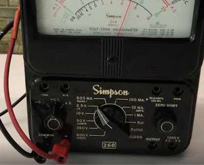
I recently found my father's old Simpson 260 meter.  He let me borrow it anytime I wanted with the warning of "DON'T COOK IT!".   My memory recalls only using it for continuity and batteries which is good because I did not have a clue as to what would "cook it".  I decided to put this heirloom to use as an internet monitor.  This project is amazingly useful and simple to duplicate.

-----

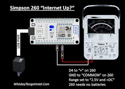
The rig uses an ESP8266 to ping different servers.   The ping time (in mS) is displayed on the Simpson 260 and 'percent of full scale'.   In other words a ping of 73mS would be 73% of full scale on the Simpson 260.    We set the source code (see below) to cycle through ten servers and show the ping result every 15 seconds.

-----

If the LAN is down or a ping error is detected the meter "wags" back and forth 5 times and tries another server.   The message to the house is, "If the needle ain't wagging back and forth then your problem ain't with the internet connection!"

-----

Upload the Arduino IDE based source code below to the ESP8266.  Connection to the Simpson 260 is easy. 
 

-----

/*
 *  A vintage Simpson 260 meter to shows network PING times
 *  and if there is a connection to the internet.
 *  
 *  Deflect the Simpson meter from 0-100% of the 2.5V full scall
 *  based on ping times of servers.
 *  
 *  10mS = 10% of full scale.   
 *  45mS = 55% of full scale.
 *  73mS = 73% if full scale.
 *  XXmS = XX% of full scale, etc....
 *  Anything over 100ms is consider terrible and just maxes to 100%
 *  
 *  A bad ping (site not found, network down, etc) will 'wag' the meter
 *  back and forth from 0% to 100% five times then try next ping site.
 *
 *  ESP8266 NodeMCU Board BAUD 115200
 *  HiLetgo 1PC ESP8266 NodeMCU CP2102 ESP-12E Development Board from Amazon
 *  
 *  Full documetation at:
 *  WhiskyTangoHotel.Com    
 *  
 *  FEB2022
 *  
 */

#include <ESP8266WiFi.h>
#include <Pinger.h>

const char* ssid     = "Virus-2.4";      // These vars are your private WIFI
const char* password = "zenakelsocats";  // connection information

// Define some 'ping friendly' sites.   ARRAY starts a 0
String PingSite[] = {  
  "whiskeytangohotel.com",
  "google.com",
  "yahoo.com",
  "bing.com",
  "abc.com",
  "cbs.com",
  "cnn.com",
  "apple.com",
  "pingler.com",
  "mailinator.com"
};  // end ping array define

int Number_of_Ping_Sites = 10;   // counted from the list above
int Secs_Between_Pings = 15;
float Min_Ping_Result = 999;
const int PINGOUT = 2;   // Drives the S260. Blue onboard LED and ~D4
Pinger pinger;

void setup() {
  analogWrite(PINGOUT, 0);
  delay(50);
 
  Serial.begin(115200);
  delay(100);

  // Connect to the WiFi network
  Serial.println();
  Serial.println();
  Serial.print("Connecting to ");
  Serial.println(ssid);

  WiFi.begin(ssid, password);

  while (WiFi.status() != WL_CONNECTED) {
    delay(500);
    Serial.print(".");
  }

  Serial.println("");
  Serial.println("WiFi connected");  
  Serial.println("IP address: ");
  Serial.println(WiFi.localIP());

// For the ping dot h features https://github.com/bluemurder/esp8266-ping
  pinger.OnEnd([](const PingerResponse& response)
  {
    // Print time information
    if(response.TotalReceivedResponses > 0)
    {
      Serial.printf("Approximate round trip times in milli-seconds:\n");
      Serial.printf(
        "    Minimum = %lums, Maximum = %lums, Average = %.2fms\n",
        response.MinResponseTime,
        response.MaxResponseTime,
        response.AvgResponseTime);
        Min_Ping_Result = response.MinResponseTime;
    }
    
    // Print host data
    Serial.printf("Destination host data:\n");
    Serial.printf(
      "    IP address: %s\n",
      response.DestIPAddress.toString().c_str());
    if(response.DestMacAddress != nullptr)
    {
      Serial.printf(
        "    MAC address: " MACSTR "\n",
        MAC2STR(response.DestMacAddress->addr));
    }
    if(response.DestHostname != "")
    {
      Serial.printf(
        "    DNS name: %s\n",
        response.DestHostname.c_str());
        
        Serial.println("Minimum ping was: " + String(Min_Ping_Result) + "mS." + " Meter to " + String(int(Min_Ping_Result)) + "% of full scale.");
        Serial.println("Delay to next ping is " + String(Secs_Between_Pings) + " seconds...");
        Serial.println("---------------------");
    }
    return true;        
  });  // end ping features

  //Self Test the meter by moving the meter full scale
  // Increase meter value and on board LED brightness
  for(int dutyCycle = 0; dutyCycle < 200; dutyCycle++){   
    // changing the LED brightness with PWM;
    analogWrite(PINGOUT, dutyCycle);
    Serial.println(String(dutyCycle) + " increasing meter self test...");
    //analogWrite(PINGOUT, testval);
    delay(10);
  }   // end meter increase
 
  // Decrease meter value and on board LED brightness
  for(int dutyCycle = 200; dutyCycle > 0; dutyCycle--){
    // changing the LED brightness with PWM
    analogWrite(PINGOUT, dutyCycle);
    Serial.println(String(dutyCycle) + " decreasing meter self test...");
    //analogWrite(PINGOUT, testval);
    delay(10);
  }  // end meter decrease  
  Serial.println("Self test complete!!!");
  Serial.println("---------------------");
 
}   // end void setup

// dutytCycle/2 = ~ the % of 2.5V scale on S260
//    0 dutytCycle =
//   50 dutytCycle = 28%
//  100 dutytCycle = 53%
//  150 dutytCycle = 77%
//  200 dutytCycle = 100%

// Set S260 to +DC.  The + lead to D4.  Neg lead to GND

void loop() {    // loop until the Cowboys win a Super Bowl

  for (int i = 0; i <= (Number_of_Ping_Sites - 1); i++) {  // don't always use the same PingSite; cycle them.
      Serial.println("PingSite[" + String(i) + "]: " + PingSite[i]);
            
      if(pinger.Ping(PingSite[i]) == false)
      {    
         Serial.println("Error during ping command.  Walk the meter 5 times.");
         // Walk the meter back and forth to symbol 'ping error' or network down    
          for (int walk = 0; walk<=4; walk++) {
              // Increase meter value and on board LED brightness
              for(int dutyCycle = 0; dutyCycle < 200; dutyCycle++){   
                // changing the LED brightness with PWM;
                analogWrite(PINGOUT, dutyCycle);
                Serial.println(String(dutyCycle) + " Showing FAIL increasing for: " + PingSite[i]);
                delay(10);
              }   // end fail meter increase
            
              // Decrease meter value and on board LED brightness
              for(int dutyCycle = 200; dutyCycle > 0; dutyCycle--){
                // changing the LED brightness with PWM
                analogWrite(PINGOUT, dutyCycle);
                Serial.println(String(dutyCycle) + " Showing FAIL decreasing for: " + PingSite[i]);
                delay(10);
              }  // end fail meter decrease
          } // end for fail meter back forth walk          
      }  // end if pinger.Ping       

      // Write Ping value to the meter.  Low is better.
      // We basically make percent of full scale equal the ping in mS, ie; 45mS = 45%...
      // Anything over a 100mS is a crappy ping so we make 100mS (100% of scale)
      if (Min_Ping_Result > 100) { Min_Ping_Result = 100; }
      
      analogWrite(PINGOUT, Min_Ping_Result * 2);  // move to meter to display the ping value
      delay(Secs_Between_Pings * 1000);   // delay for next ping    
  }  // end for/next to cycle the PingSites             
}  // end loop until the Cowboys win the Super Bowl
-----

Monday, February 7, 2022

Retirement Clock Goes Digital


-----

We overheard in a conversation recently something like: "Now that I'm retired I really only focus on what day of the week it is and the general time of day."  We then discovered this awful looking Day of the Week Clock and the vision of a more modern version came to mind.

-----

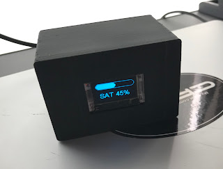
The rig is based around this MakerFocus ESP32 Development Board mainly because it works with the Arduino IDE and has WiFi with a display on board.   The code (source below) gets it's time/date from a NTP server and then simply figures out and displays the day of the week and what percentage of the day has past.  Evidently this is all the critical information needed to guide the non-working through their day.

-----

To dress up the look a case was 3D printed.  After seeing the result we needed to celebrate with a beer.   As shown in the video below it was a bit early in the day for a drink, but as the ol' saying goes "It's 71% somewhere!".

-----

Retirement Clock Source Code:

/*
 * HelTec Automation(TM) ESP32 Series Dev boards OLED "Retirement Clock"
 * Adruino IDE Board Setting: WiFi Kit32, Disabled, 240MHz, 921600, None
 *
 * "Retirement Clock" shows only Day of Week and percentage time left in the day.
 *  
 * FEB 2022
 * Search whiskeytangohotel.com for project details.
 *
*/

#include "Arduino.h"
#include "heltec.h"

#include <TimeLib.h>
#include <WiFi.h>
#include <WiFiUdp.h>

const char ssid[] = "xxxxxxx";  //  your network SSID (name)
const char pass[] = "xxxxxxx";       // your network password
long Sync_Delay = 60000;  //  60000 is sync every ten minutes,  We aren't going for precision here. LOL

int DOWNUM = 0;     //  DOWNUM from NTP (expect 0 - 6)
String DOW = "DOW";  // DOWNUM to a Day of Week String
int hourNUM = 0;    //  hour() value from NTP
float minuteNUM = 0;   // minute() value from NPT

// NTP Servers:
static const char ntpServerName[] = "pool.ntp.org";
const int timeZone = 0;     // leave as 0 for UTC.  We do the offset math in void setup

WiFiUDP Udp;
unsigned int localPort = 8888;  // local port to listen for UDP packets

time_t getNtpTime();
void digitalClockDisplay();
void printDigits(int digits);
void sendNTPpacket(IPAddress &address);

void setup() {
  //NTP setup
  Serial.begin(115200);
  while (!Serial) ; // Needed for Leonardo only
  delay(250);
  Serial.println("TimeNTP");
  Serial.print("Connecting to... ");
  Serial.println(ssid);
  WiFi.disconnect();
  WiFi.mode(WIFI_MODE_STA);
  WiFi.begin(ssid, pass);

  while (WiFi.status() != WL_CONNECTED) {
    delay(500);
    Serial.print(".");
  }

  Serial.print("IP number assigned by DHCP is: ");
  Serial.println(WiFi.localIP());
  Serial.println("Starting UDP");
  Udp.begin(localPort);
  Serial.print("Local port: ");
//  Serial.println(Udp.localPort());
  Serial.println("waiting for sync... ");
  setSyncProvider(getNtpTime);
  setSyncInterval(Sync_Delay);  //   defines how often to check NTP time

  // Hetec setup
  Heltec.begin(true /*DisplayEnable Enable*/, false /*LoRa Disable*/, true /*Serial Enable*/);
  Heltec.display->flipScreenVertically();
  Heltec.display->setFont(ArialMT_Plain_24);
} // end setup link

time_t prevDisplay = 0; // when the digital clock was last displayed timer

void loop() {   // main program loop
  if (timeStatus() != timeNotSet) {
    if (now() != prevDisplay) { //update the display only if time has changed
      prevDisplay = now();
    }
  }

  // Parse time info and send info to serial monitor (for debug)
  Serial.print(hour());
  printDigits(minute());
  printDigits(second());
  Serial.print(" ");
  Serial.print(day());
  Serial.print(".");
  Serial.print(month());
  Serial.print(".");
  Serial.print(year());
  Serial.print(" : ");

  if (int(year()) < 2022) {
     Serial.print(String(int(year())) + " is the NTP server year.  That aint right, so try again!!!");
     Serial.println();      
     setup();
  }   // the NTP server return something 'wierd' (probably 1970) so try again  

  //Covert Time in percent of day completed.  Midnight Local = 0%, Noon Local = 50%  
  minuteNUM = minute();
  hourNUM =   int(hour());  
  // manually adjust hourNUM and minuteNUM for debug
  // hourNUM =  5;    // valid values are INTERGERS 0 thru 24
  // minuteNUM = 49;    // valid values are INTEGERS 0 thru 60  

  minuteNUM = minuteNUM / 60;    // covert minutes to 'fraction'  
  hourNUM = hourNUM - 6;   // hourNUM is in UTC.   Adjust to local.   -6 = CST, -5 = CDT, 0 = UTC
  DOWNUM = int(weekday());
   
  // Calculate percentage of the day pasted into 'progress'
  int progress = round(   (  ((hourNUM + minuteNUM))   /  24   )  * 100    );
  if (progress < 0) {   // it's past UTC midnight and the timezone offset created a negative %
    progress = 100 + progress;
    DOWNUM = DOWNUM -  1;
  }  //end progress < 0

  // Convert DOWNUM into printable String.  Sunday is 1
  if (DOWNUM  == 1) { DOW = "SUN"; }
  if (DOWNUM  == 2) { DOW = "MON"; }
  if (DOWNUM  == 3) { DOW = "TUE"; }
  if (DOWNUM  == 4) { DOW = "WED"; }
  if (DOWNUM  == 5) { DOW = "THU"; }
  if (DOWNUM  == 6) { DOW = "FRI"; }
  if (DOWNUM  == 7) { DOW = "SAT"; }

  Serial.print(String(int(weekday())) + " is " + DOW);
  Serial.println();   
  Serial.print(String(hourNUM) + " + " + String(minuteNUM) + " = " + String(progress) + "%");
  Serial.println();
 
  // clear the display
  Heltec.display->clear();

  // Draw the Precent of Day pasted onto progress bar
  Heltec.display->drawProgressBar(0, 0, 127, 20, progress);

  // Label the Day Of Week and percentage as String
  Heltec.display->setTextAlignment(TEXT_ALIGN_CENTER);
  Heltec.display->drawString(60, 31, DOW + " " + String(progress) + "%");
  // Write buffer to Heltec display
  Heltec.display->display();
 
  delay(5000); // wait some.  we are in no hurry to update the screen
}  // end void loop main program


void printDigits(int digits)
{
  // utility for digital clock display: prints preceding colon and leading 0
  Serial.print(":");
  if (digits < 10)
    Serial.print('0');
  Serial.print(digits);
}

/*-------- NTP code ----------*/

const int NTP_PACKET_SIZE = 48; // NTP time is in the first 48 bytes of message
byte packetBuffer[NTP_PACKET_SIZE]; //buffer to hold incoming & outgoing packets

time_t getNtpTime()
{
  IPAddress ntpServerIP; // NTP server's ip address

  while (Udp.parsePacket() > 0) ; // discard any previously received packets
  Serial.println("Transmit NTP Request");
  // get a random server from the pool
  WiFi.hostByName(ntpServerName, ntpServerIP);
  Serial.print(ntpServerName);
  Serial.print(": ");
  Serial.println(ntpServerIP);
  sendNTPpacket(ntpServerIP);
  uint32_t beginWait = millis();
  while (millis() - beginWait < 1500) {
    int size = Udp.parsePacket();
    if (size >= NTP_PACKET_SIZE) {
      Serial.println("Receive NTP Response");
      Udp.read(packetBuffer, NTP_PACKET_SIZE);  // read packet into the buffer
      unsigned long secsSince1900;
      // convert four bytes starting at location 40 to a long integer
      secsSince1900 =  (unsigned long)packetBuffer[40] << 24;
      secsSince1900 |= (unsigned long)packetBuffer[41] << 16;
      secsSince1900 |= (unsigned long)packetBuffer[42] << 8;
      secsSince1900 |= (unsigned long)packetBuffer[43];
      return secsSince1900 - 2208988800UL + timeZone * SECS_PER_HOUR;
    }
  }
  Serial.println("No NTP Response :-(");
  return 0; // return 0 if unable to get the time
}

// send an NTP request to the time server at the given address
void sendNTPpacket(IPAddress &address)
{
  // set all bytes in the buffer to 0
  memset(packetBuffer, 0, NTP_PACKET_SIZE);
  // Initialize values needed to form NTP request
  // (see URL above for details on the packets)
  packetBuffer[0] = 0b11100011;   // LI, Version, Mode
  packetBuffer[1] = 0;     // Stratum, or type of clock
  packetBuffer[2] = 6;     // Polling Interval
  packetBuffer[3] = 0xEC;  // Peer Clock Precision
  // 8 bytes of zero for Root Delay & Root Dispersion
  packetBuffer[12] = 49;
  packetBuffer[13] = 0x4E;
  packetBuffer[14] = 49;
  packetBuffer[15] = 52;
  // all NTP fields have been given values, now
  // you can send a packet requesting a timestamp:
  Udp.beginPacket(address, 123); //NTP requests are to port 123
  Udp.write(packetBuffer, NTP_PACKET_SIZE);
  Udp.endPacket();
}

-----

Wednesday, February 26, 2020

ESP8266 Doorbell Sends SMS and Updates Google Sheet

-----
On-line shopping has changed the way goods are acquired.  For most packages it is not necessary to be around for the dropoff.  But... for the important stuff it is.  Those packages always seem to show up right when you are in the backyard for mere seconds causing that frustrating "Personal Signature Required for Delivery" note on the door.  This is our DIY effort to solve that problem.
-----
Needed:
     - ESP8266 (microcontroller with WiFi)
     - 1M ohm resistor
     - reed switch
     - IFTTT account (using the WebHook applet)
     - wire and stuff
     - fundamental knowledge on Arduino sketches (simple code edits).
-----
The connections are simple:

 ----
And the rig will look something like this:
-----
A 1M ohm resister connected from 3.3V to the A0 [ADC] input on the ESP8266 keeps the A0 reading at maximum value.   The normally open reed switch is placed right on top of the coils that activate the doorbell.  These coils act like that electromagnet you build in grade school to ring the doorbell and cause the reed switch to close.  This drops the impedance to the 1M resistor and changes the ADC value on the A0 pin for detection of the doorbell.  Then the SMS is sent to your phone and a Google Drive Sheet is updated.
-----
-----
The sketch you need to upload to the the ESP8266 looks like this:
```````````````````````````````````````````````````````````````````````````````
/*
 *  FEB2020
 *  Door Bell Monitoring
 *  WhiskeyTangoHotel.Com
 * 
 *  Build details at:
 *  http://www.whiskeytangohotel.com/2020/02/esp8266-doorbell-sends-sms-and-updates.html
 * 
 *  On Doorbell ring:
 *    Logs to Google Drive (as an appending spreadsheet)
 *    Sends SMS to cell phone
 * 
 *  ESP8266 uC
*/

// For the Wireless
#include <ESP8266WiFi.h>

// WiFi Connection Information
const char* ssid = "yourssid";    // PRIVATE: Enter your personal setup information.
const char* password = "yourwifipassword"; // PRIVATE: Enter your personal setup information.

// IFTTT Information for WebHook widget
String MAKER_SECRET_KEY = "yourIFTTTprivatekey";  // PRIVATE: Enter your personal setup information. Your IFTTT Webhook key here
String TRIGGER_NAME_google_drive = "googlebell";    // this is the Maker IFTTT trigger name for google drive spreadsheet logging
String TRIGGER_NAME_SMS = "doorbell";              // this is the Maker IFTTT trigger name to send SMS.
const char* host = "maker.ifttt.com";
String url_SMS;                      // url that gets built for the IFTTT Webhook sending SMS
String url_google_drive;            // url that gets built for the IFTTT Webhook logging to google drive spreadsheet
String Status ="**_Starting_on:";  // Status payload for Google Sheet.  We log all starts and reboots

// Define and set up some variables
int sensorValue = 0;  // reading from A0.  This pin detects the doorbell (ADC reading between 0-1024)

// Define pins
const int led = 2;     // Blue on board LED is on PIN2.  Active LOW.  Blinks it between reads
const int bell = A0;  // analog input for the doorbell transducer. 1MOhm on board in // with 1MOhm from the reed switch pickup

// Program control variables
int Seconds_dwell_after_detect = 8;  // Prevents logging flood and debounce.   Sensor reads, LED flashing, etc.
int logging = 1; // If 1 then SMS and log to cloud.  Any other value (0) turns it off.

void setup(){  // This is run once.
  pinMode(led, OUTPUT);  // set up the onbaord LED pin as an output.    
  Serial.begin(115200);  // turn on the serial monitor for debug

  // wait until serial port opens for native USB devices
  while (! Serial) {
    delay(10);
  }
 
  // Is the WiFi working?
  WiFi.begin(ssid, password);
  Serial.println("");
  // Wait for connection
  while (WiFi.status() != WL_CONNECTED) {
    Serial.print("Trying to connect to ");
    Serial.print(ssid);
    Serial.print(" on ");
    Serial.println(WiFi.localIP());
    for (int x = 0; x < 20; x++) { // 
      digitalWrite(led, !digitalRead(led));  // toggle state of the on board blue LED. Shows program is trying to WiFi connect
      //Serial.println("Server Start blink loop....");
      delay(5);   // Delay so short the LED looks like it is always on
    } // endfor WiFi blink connect
  }
  Serial.print("Connected to ");
  Serial.println(ssid);
  Serial.println(WiFi.localIP());

  for (int x = 0; x < 10; x++) { // 5 slow LED blinks to slow WIFI Connected.
  digitalWrite(led, !digitalRead(led));  // toggle state of the on board blue LED.
  Serial.println("WIFI is Connected....");
  delay(500);   } // endif for WIFI Connected blink


  // Use WiFiClient class to create TCP connections for WiFi logging
  WiFiClient client;
  const int httpPort = 80;
  if (!client.connect(host, httpPort)) {
    Serial.println("connection failed");  // Boo!!!
    return;
  }

  // Trigger the IFTTT Webhook Channel to update a Google sheet with the activity of the server starting/restarting
  // This can help log power outs, etc.  For first run we defined String Status for identify a startup condition.
  // Create the request for IFTTT google drive
  url_google_drive = "https://maker.ifttt.com/trigger/" + TRIGGER_NAME_google_drive + "/with/key/" + MAKER_SECRET_KEY + "?value1=" + String(Status);
  Serial.println (url_google_drive);
  Serial.println(" "); 
   
  // This sends the request to the IFTTT server
  client.print(String("POST ") + url_google_drive + " HTTP/1.1\r\n" +
  "Host: " + host + "\r\n" +
  "Connection: close\r\n\r\n"); 
  delay(500);  // Delay for web traffic; maybe not required. 

  // Read all the lines of the reply from server and print them to Serial
  while(client.available()){
     String line = client.readStringUntil('\r');    }

  String Status = "Payload_String_for_Google_Sheet";
}
 
void loop(){   // Loop forever or until the Dallas Cowboys win a Super Bowl
  // Read the A0 pin and post based on the delay values set above.
  // The blue onboard LED will fast blink while polling
  sensorValue = analogRead(bell);
  //Serial.println (sensorValue);   //debug only

  // Fast Blink Blue LED while waiting for doorbell press
  digitalWrite(led, !digitalRead(led));  // toggle state of the on board blue LED. Shows program is running
  Serial.println("Waiting for DoorBell....");
  delay(50);   

  // Use WiFiClient class to create TCP connections for IFTT
  WiFiClient client;
  const int httpPort = 80;
  if (!client.connect(host, httpPort)) {
    Serial.println("connection failed");
    return;
  }
 
  if (sensorValue < 200 || sensorValue > 300) {  //  A0 values between 200-300 are normal.  Increases (apprx doubles) when DB is pressed
      Serial.println("----------Doorbell Dectected----------");

      if (logging == 1) { // is logging turned on? Non "1" is for debug...  Typically would be set = 1
        Serial.println("***** Logging is ON *****");

        // Build the IFTTT Webhoo Channel for SMS url
        url_SMS = "https://maker.ifttt.com/trigger/" + TRIGGER_NAME_SMS + "/with/key/" + MAKER_SECRET_KEY;
        client.print(String("POST ") + url_SMS + " HTTP/1.1\r\n" +
        "Host: " + host + "\r\n" +
        "Connection: close\r\n\r\n");
        Serial.println(" ");
        Serial.println("SMS payload to IFTTT is:");
        Serial.println(url_SMS);   
        Serial.println(" ");  

        // This must be run before any IFTTT webhook
        const int httpPort = 80;
        if (!client.connect(host, httpPort)) {
          Serial.println("connection failed");
          return;
        }
           
        // Set up IFTTT Webhook Channel to update a Google sheet with the activity. 
        Status ="__Doorbell_on:";
        url_google_drive = "https://maker.ifttt.com/trigger/" + TRIGGER_NAME_google_drive + "/with/key/" + MAKER_SECRET_KEY + "?value1=" + String(Status);
        client.print(String("POST ") + url_google_drive + " HTTP/1.1\r\n" +
        "Host: " + host + "\r\n" +
        "Connection: close\r\n\r\n");
        Serial.println(" ");
        Serial.println("IFTTT url payload to Google Drive is:");
        Serial.println(url_google_drive);
        Serial.println(" ");
   
      } else {   // We are not sending to IFTTT.  Debug mode
         Serial.println("Logging is OFF.");
         Serial.println(" ");
      } // endif/else logging 
   
    for (int x = 0; x < Seconds_dwell_after_detect*2; x++) { // DoorBell dectected. Pause and LED flash for visual acknowledgement
      digitalWrite(led, !digitalRead(led));  // toggle state of the on board blue LED
      Serial.println("Doorbell dectected,  Now in BLINK Loop....");
      delay(500);   } // endfor DoorBell Dwell loop  
       
  }   // end doorbell A0 pressed
}  // end of endless loop
-----
That's it and thanks for stopping by!!!

Friday, January 6, 2017

ESP8266 WiFi Garage Door Opener from any Web Browser

The 'brain' is the ESP8266 uC.  It is available with on board WiFi and plenty of I/O for smaller projects.  All this for well under $10USD with programming options for NodeMCU, MicroPython, and the Arduino IDE.
-----
There seems to be an unstoppable drive in the hacker DIY community for web based garage door openers and we were compelled to respond.  The garage door opener we have opens/shuts from a push button switch that basically creates a short to connect two terminals on the garage door opening unit.  That allows easy implementation because all that is required is a ESP8266 controlled relay wired across those two terminals to create a switch closure.

In addition to activating the door any activity is logged to a Google Sheet via the IFTTT.com Maker Channel.  This is handy to track all activation usage and ESP8266 server restarts.
-----
The main components are the ESP8266, a relay module, a BS170 N-Channel MOSFET.
 
-----
Simple.  Connect the 'stuff' as shown in the schematic:
and it will look something like this:
----
Use the Arduino IDE to load the source code below into the ESP8266 then wire the Normally Open (NO) side of relay you are controlling to the two terminals on the garage door opener that active the motor when 'shorted' together.

A few comments on the application:
  • Control works from Android, iPhone, PC, etc.  Basically any browser.  In the source code below if a device can open "http://192.168.0.28/long_confusing_URL_to_activate_relay" it will activate the garage door.
  • There is a "TEST" URL in the source code (http://192.168.0.28/) that confirms the ESP8266 is online but does not activate the door.
  • Set a static IP for the ESP8266 in your WiFi router.  Otherwise it may be assigned a different local IP if the ESP8266 or WiFi router is restarted.
  • Use long/complex URLs.  That way those that are connected to your router don't have a 'obvious' URL to activate the rig or one they can remember if you demo it.
  • We only wanted control of the door when connected to the host WiFi router locally (LAN) and not from anyplace on the planet.  If you want extended control to the WWW open a port on your router, but be aware of the concerns. We wanted to limit use only to those authorized to connect the WiFi router locally (LAN).  Plus, we didn't want to risk accidentally activating the door from a remote location.
  • The source code has separate IFTTT.com Maker Channel triggers to log events.  We could use one Maker Channel trigger and just pass different GETPOST variables.  However, creating multiple Maker Channel triggers would easily allow usage tracking on individuals by assigning each one a unique trigger name. (/ZenaActivate, /KelsoActivate, etc...)
  • Any time the door is activated or the ESP8266 is restarted (power outage, etc) a Google Sheet is updated to log the event as shown below. 
 
-----
The Arduino IDE source code is:

/*
 *  Garage Door Opener via Web Browser and log to IFTTT.com
 *  ESP8266 NodeMCU Board using Arduino IDE
 *  WhiskyTangoHotel.Com    DEC2106
 * 
 *  Blue on board LED is active LOW on GPIO2 (D4 on silkscreen)
 *  Relay to control Garage Door is active HIGH on GPIO5 (D1 on silkscreen)
 * 
 *  Opening 192.168.0.28/long_confusing_URL_to_activate_relay is called.  Every effort is made to keep the relay off 
 *  so the door does not close/activate by accident.
 * 
 *  A 'test' message is display on browser to see if server is up by calling root at:.
 *  192.168.0.28/  This WILL NOT ACTIVATE THE RELAY.  Only tests the server
 * 
 *  The 'meat' is at 192.168.0.28/long_confusing_URL_to_activate_relay. This will send a msg to the browser AND open/close the door.
 * 
 */

#include <ESP8266WiFi.h>
#include <WiFiClient.h>
#include <ESP8266WebServer.h>
#include <ESP8266mDNS.h>

// WiFi Information
const char* ssid = "YOUR-SSID";
const char* password = "ASCII-PASSCODE-FOR-YOUR-SSID";

// IFTTT Information
String MAKER_SECRET_KEY = "xxx-yyy-zzz-123-456-789"; // your maker key here
String TRIGGER_NAME = "IFTTT_Maker_name_to_activate_relay";  // this is the Maker IFTTT trigger name for relay activation
const char* host = "maker.ifttt.com";

ESP8266WebServer server(80);

// Output pins
const int led = 2;  // Blue on board LED
const int relay = 5;  // Relay control line

int randNumber;  // Random# generated just to show a change in the screen.  Help to verify updated page call.

void handleRoot() {
  // This is called if 192.168.0.28/ is requested.  The root.
  // The 'meat' is at /long_confusing_URL_to_activate_relay.
  // This is just here to test the ESP8266 connectivity of the WiFi network without moving the relay
  // Show a message and flash the on board LED.
  randNumber = random(1, 10000);  // Random number just to show a change on the webpage at reload.
  server.send(200, "text/plain", "Testing ESP8266.  Response is: " + String(randNumber));
  digitalWrite(led, 0);  // Active LOW.  Turn On board LED On
  delay(2000);
  digitalWrite(led, 1);  // Active LOW.  Turn On board LED Off
}

void handleNotFound(){
  digitalWrite(led, 1);  // Keep the LED off.
  digitalWrite(relay, 0);  // Keep Relay OFF
  String message = "File Not Found\n\n";
  message += "URI: ";
  message += server.uri();
  message += "\nMethod: ";
  message += (server.method() == HTTP_GET)?"GET":"POST";
  message += "\nArguments: ";
  message += server.args();
  message += "\n";
  for (uint8_t i=0; i<server.args(); i++){
    message += " " + server.argName(i) + ": " + server.arg(i) + "\n";
  }
  server.send(404, "text/plain", message);
}

void setup(void){
  pinMode(led, OUTPUT);
  pinMode(relay, OUTPUT);
  digitalWrite(led, 1);  // LED Off
  digitalWrite(relay, 0);  // on power to relay
  Serial.begin(115200);  // serial prints to PC for debug use only
  WiFi.begin(ssid, password);
  Serial.println("");

  // Wait for connection
  while (WiFi.status() != WL_CONNECTED) {
    delay(1000);
    Serial.print("Trying to connect to ");
    Serial.print(ssid);
    Serial.print(" on ");
    Serial.print(WiFi.localIP());
    Serial.println(".");
  }
  Serial.println("");
  Serial.println("");
  Serial.print("Connected to ");
  Serial.println(ssid);
  Serial.println(WiFi.localIP());

  if (MDNS.begin("esp8266")) {
    Serial.println("MDNS responder started");
 
  // Write to Google Sheet via IFTTT Maker channel that the ESP8266 has started/restarted

  // Now we trigger the IFTTT Maker Channel to update a Google sheet with the activity of the server starting/restarting
  // This can help log power outs, etc. 
  // Use WiFiClient class to create TCP connections
  WiFiClient client;
  const int httpPort = 80;
  if (!client.connect(host, httpPort)) {
    Serial.println("connection failed");
    return;
  }
 
  // Create the request for IFTTT GARAGE_trigger_serverstart.  This can help log power outs, etc.
  String url = "https://maker.ifttt.com/trigger/GARAGE_trigger_serverstart/with/key/" + MAKER_SECRET_KEY;
  Serial.print("Requesting URL: ");
  Serial.println(url);
 
  // This sends the request to the IFTTT server
  client.print(String("POST ") + url + " HTTP/1.1\r\n" +
  "Host: " + host + "\r\n" +
  "Connection: close\r\n\r\n");
 
  delay(500);  // Delay to for web traffic; maybe not required.
  }

  server.on("/", handleRoot);

  server.on("/long_confusing_URL_to_activate_relay", [](){
    // This is called when 192.168.0.28/long_confusing_URL_to_activate_relay is called
    randNumber = random(1, 10000);  // Random number just to show a change on the webpage at reload.
    server.send(200, "text/plain", "Relay activated @ESP8266.  Code: " + String(randNumber));
    digitalWrite(led, 0);  // Active LOW.  Turn On board LED On
    digitalWrite(relay, 1);  // Relay ON

    // Know we trigger the IFTTT Maker Channel to update a Google sheet with the activity. 
    // Use WiFiClient class to create TCP connections
    WiFiClient client;
    const int httpPort = 80;
    if (!client.connect(host, httpPort)) {
      Serial.println("connection failed");
      return;
    }
 
    // Create the request for IFTTT
    String url = "https://maker.ifttt.com/trigger/" + TRIGGER_NAME + "/with/key/" + MAKER_SECRET_KEY;
    Serial.print("Requesting URL: ");
    Serial.println(url);
 
    // This sends the request to the IFTTT server
    client.print(String("POST ") + url + " HTTP/1.1\r\n" +
    "Host: " + host + "\r\n" +
    "Connection: close\r\n\r\n");
   
    delay(2000);  // Delay to keep the relay closed.
    digitalWrite(led, 1);  // Active LOW.  Turn On board LED Off
    digitalWrite(relay, 0);  //Relay OFF
  });

  server.onNotFound(handleNotFound);

  server.begin();
  Serial.println("HTTP server started");
}

void loop(void){
  server.handleClient();
}
-----