
Complete wiring diagrams, parts list, and PICAXE source code provided below.
The greatest thing about the OWI Edge Robot Arm is that you assembly it yourself so you understand it well and it is easy to customize.
Intrigued by the idea having a robot that I could personally program to do my evil bidding was overwhelming. Just imagine the possibilities..... Also, I am lucky enough to have a sister that was willing to give an adult a child's toy as a Christmas gift.

The Objective: Replace the wired control box with a programmable microcontroller to let the OWI Edge Robot Arm run autonomously.
In the end, the project results were in some ways underwhelming. Due to the lack of position feedback and the "slack" in the gear/joint movement mechanics it is impossible to control the robot with any precision. In other words, if you move an axis one direction for 1.5 seconds it does not mean it will be in the original starting position if you simple reverse the movement for 1.5 seconds.
That said, having a controllable robot is still pretty cool and it does make a excellent platform to to demonstrate motor drive and control capability with a microcontroller.
Let's go through the build....
The following hardware was chosen because it is cheap, easy to use, and readily available:
- OWI Edge Robot Arm (it that is not obvious then stop reading now)
- Three SN754410NE motor driver ICs to supply the drive current to the DC motors.
- One PICAXE 20M2 to control which direction to spin the motors.
- A "strong" 5VDC power source.
-----

Let's take a look at the SN754410NE motor driver IC. First, why is it even required? Motors draw a lot of current. The motors on the OWI Robot measured up to 800mA at full load. That's way too much current to expect from a microcontroller output to drive, so the SN754410NE is required to supply that current. The outputs of the PICAXE 20M2 are programmed to "tell" the SN754410NE motor driver what direction to spin the robot's motors.
Understanding the SN754410NE is simple and straight forward in the configuration we want to use it in. Take a look at the SN754410NE pinout diagram:

One SN74410NE motor driver can control two DC motors to spin in any direction you like; clockwise or counter clockwise. Sure, there are 16 legs on this SN74410NE motor driver chip to wire, but not to worry. If you break it down it is simple. The designers were clever and grouped all the legs for one motor on one side and the legs for other motor on the opposite side. And really, for this application all but four wires on each side are connected to power (+5VDC) or ground. So really, you are only concerned about connecting four "special" connections per motor used. Two will go to the motor and two will go to the PICAXE 20M2 microcontroller.
---
So connecting one motor to the "lower" legs of the SN74410NE motor driver IC will look like this:

See; it's easy. Most legs of the SN74410NE motor driver are connected to +5VDC and ground.
To +5VDC: Legs 1, 16. Legs 8, 9
To GND: Legs 4,5. Legs 12, 13
As for the four "special" connections mentioned above:
Legs 3 and 6 connect to the motor.
Legs 2 and 7 will go the the PICAXE 20M2 microcontroller (more on that later).
Let's point out how the SN74410NE motor driver works:
Condition of Leg 3 Condition of Leg 6 What does the motor do?
------------------ ------------------ -------------------------
0 Volts 0 Volts Motor does not spin
0 Volts 5 Volts Motor spins Clockwise
5 Volts 0 Volts Motor spins Counter Clockwise
5 Volts 5 Volts Motor does not spin
Basically what the table is trying to show is that if Leg 3 and Leg 6 have different voltages the motor will spin. If Leg 3 and Leg 6 have the same voltage the motor will stop. You can "test" this before you connect the PICAXE microcontroller if you like by just connecting the legs straight to the supply voltage and ground. Later, the PICAXE 20M2 will be programmed and connected to control the motor (stay tuned).
But wait, the OWI Edge Robot Arm has five motors and the SN74410NE motor driver can only control two motors. That's no problem if three SN74410NE are used.
----
Below is what the three SN74410NE motor driver ICs look like on a breadboard after the power and grounds are connected. Six motors can be controlled with this set up. Only five motors are needed so we will not connect a motor to the upper side of the right most SN74410NE motor driver.

-----
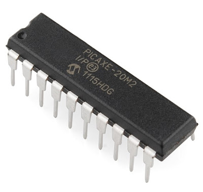
Let's move from discussing the SN754410NE motor driver IC and switch to controlling how the motors spin control with a custom programmed PICAXE 20M2 microcontroller.
The PICAXE 20M2 is a low cost microcontroller (less than $4) that is easy to program for this application. To control five motors we need 10 outputs; two outputs for each of the five motors. The PICAXE 20M2 has 18 outputs and that is plenty.

-----
Notice how the PICAXE 20M2 legs are labeled; b.7, b.6, etc. The drawing below shows how to wire up the whole system. It shows where to wire power and ground. It shows where wire the motors. It shows where to wire in the PIXACE 20M2 so it will work with the program source code below.

Again, notice nothing is connected to " upper" portion of the SN754410NE motor driver on the far right. Good engineering practice would say the inputs (Leg 10 and Leg 15) should be tied to ground. But, we aren't designing for a Mars rover or anything critical, so everything should be fine. As a general rule leaving inputs floating can lead to a risky design.
The PICAXE 20M2 is programmed (again, example source code below) to control the direction of each motor. From above we know that varying the condition of the SN754410NE motor driver IC inputs has a resulting spin on the motor. The source code for the PICAXE 20M2 simply forces the two SN754410NE motor driver IC inputs high and/or low to make the robot motor spin in the desired direction. High/Low will spin the motor one way. Low/High will spin the motor the other way. The PICAXE 20M2 output conditions are held static in the source code with the PAUSE command to determine how long the motor will spin. If the PICAXE 20M2 is programmed to output High/High or Low/Low the motor will stop moving.
----
Let's wrap this up. These wires connect to the five motors on the OWI robot:

These are the wires that go to straight to the SN754410NE motor driver ICs. If you connect these wires straight to Power and Ground you can document which connector wires control what motor and in what direction.
-----
After you wire the PICAXE 20M2 to the SN754410NE motor driver ICs your breadboard will look something like this:

-----
Add in the wires from OWI Robot motors and your done with the hardware. It will look like this:

-----
Picture of the final build with everything wired in:

-----
A short video demo of all five motors being controlled on the OWI Robot. Be aware that the motors can pull over 500mA each. Running several motors at once can demand a lot of current, so if your design doesn't work suspect the power supply may not have enough output current.
----
A below is source code for the PICAXE 20M2 to make it all work. Basically, the PICAXE 20M2 outputs are set HIGH and/or LOW to control the motors. A PAUSE statement determines how long that motor should stay on. Both outputs LOW stop the motor movement. It is possible to move more than one motor at a time if you have a 5VDC power source that can supply enough current. In the example below all motors are excerised one at a time. The code can be modified to make the OWI Robot dance to your wishes:
; *************************************
; ***** www.whiskeytangohotel.com *****
; *************************************
; Project Name: OWI Robot Arm "Nancy"
;
; Start Date: DEC 2011
;
; Program Rev History:
;
;
; *******************************
; PICAXE PE Rev: MacAXEPad 1.3.2
;
#picaxe20m2
'Define the outputs to be discriptive
symbol Grip_Close = b.0
symbol Grip_Open = b.1
symbol Wrist_Up = b.2
symbol Wrist_Down = b.3
symbol Elbow_Up = b.4
symbol Elbow_Down = b.5
symbol Shoulder_Out = b.6
symbol Shoulder_In = b.7
symbol Base_CCW = c.0
symbol Base_CW = c.1
'Subroutine move commands are:
' GripOPEN GripCLOSE GripSTOP
' WristUP WristDOWN WristSTOP
' ElbowUP ElbowDOWN ElbowSTOP
' ShoulderIN ShoulderOUT ShoulderSTOP
' BaseCCW BaseCW BaseSTOP
' StopAll
' (motion referenced from behind the robot
main:
gosub WristDOWN
gosub StopALL
pause 1000
gosub WristUP
gosub WristUP
gosub StopALL
pause 1000
gosub ElbowDown
gosub StopALL
pause 1000
gosub ElbowUP
gosub StopALL
pause 1000
gosub GripOPEN
gosub GripCLOSE
pause 1000
gosub GripOPEN
gosub GripCLOSE
gosub StopALL
pause 1000
gosub ShoulderIN
gosub StopALL
pause 1000
gosub GripOPEN
gosub GripCLOSE
pause 1000
gosub GripOPEN
gosub GripCLOSE
gosub StopALL
pause 1000
gosub ShoulderOUT
gosub StopALL
pause 1000
gosub BaseCCW
gosub StopALL
pause 1000
gosub BaseCW
gosub BaseCW
gosub StopALL
pause 1000
gosub BaseCCW
gosub StopALL
pause 1000
gosub GripOPEN
gosub GripCLOSE
pause 1000
gosub GripOPEN
gosub GripCLOSE
gosub StopALL
pause 1000
gosub WristDown
gosub StopALL
goto main
' ------GRIP------
GripOPEN:
high Grip_Open
low Grip_Close
pause 1000
return 'GripOpen
GripCLOSE:
low Grip_Open
high Grip_Close
pause 1000
return 'GripClose
GripSTOP:
low Grip_Open
low Grip_Close
return 'GripStop
'-----------------
'------WRIST------
WristUP:
high Wrist_Up
low Wrist_Down
pause 1800
return 'WristUp
WristDOWN:
low Wrist_Up
high Wrist_Down
pause 1800
return 'WristDown
WristSTOP:
low Wrist_Up
low Wrist_Down
return 'WristStop
'------------------
'------ELBOW------
ElbowUP:
high Elbow_Up
low Elbow_Down
pause 3000
return 'ElbowUp
ElbowDOWN:
low Elbow_Up
high Elbow_Down
pause 3000
return 'ElbowDown
ElbowSTOP:
low Elbow_Up
low Elbow_Down
return 'ElbowStop
'------------------
'------SHOULDER------
ShoulderIN:
high Shoulder_Out
low Shoulder_In
pause 2500
return 'ShoulderUp
ShoulderOUT:
low Shoulder_Out
high Shoulder_In
pause 2500
return 'ShoulderDown
ShoulderSTOP:
low Shoulder_Out
low Shoulder_In
return 'ShoulderStop
'------------------
'------BASE------
BaseCCW:
high Base_CCW
low Base_CW
pause 3000
return 'BaseCCW
BaseCW:
low Base_CCW
high Base_CW
pause 3000
return 'BaseCW
BaseSTOP:
low Base_CCW
low Base_CW
return 'BaseStop
'------------------
'----StopAll-------
StopAll:
gosub GripStop
gosub WristStop
gosub ElbowStop
gosub ShoulderStop
gosub BaseStop
return 'StopAll
'----------------
