For about a $1.50 USD eBay sellers will ship out to you the servo tester pictured above. It's an amazing value to let you verify that the cheap servo you also got from eBay even works. It's also great to help understand the MIN, CENTER, and MAX positions for any servo based RC or uC project.
-----
Basically, servos motors are controlled by receiving pulse train signals. The eBay servo tester is capable of producing this required pulse train. Jameco has an easy to follow tutorial. The image below shows that a 1mSec pulse width sends the servo full left. 1.5mSec centers the it. 2mSecs move the servo full right. Jameco explains it all very well.
-----
The servo tester has three setting:
MANUAL: allows the servo position to be
adjusted with a knob.
CENTER: sets the servo to it's center
position
SWEEP: continually sweeps the servo from it's MAX to MIN position (forever)
Connection is simple. One side of the servo tester is for power. The other side is where the servo under test conveniently plugs in.
-----
So.... let's use a Tektronix MSO5104B oscilloscope to look at the output of the servo tester and see what the heck is going on. In the screen shot below the servo tester control knob is set to full left (minimum). Sure enough, the pulse width as measured by the scope is 915uSec. That's pretty darn close to the 1mSec width in the drawing above.
-----
With the knob set to full right (maximum) the scope cursors show a pulse width
of 2.14mSec; pretty close to the ideal 2mSec in the drawing.
-----
Using the MSO5104B oscilloscope to zoom out on the signal we can see that the pulses repeat steadily every 20mSec. If you check the tutorial at Jameco you will know that is exactly what is expected.
----- Conclusion: Splurge the $1.50 USD and treat yourself to this handy device. It really helps to verify that a servo is actually working and in setting the movement limits on your project. Below are two short videos of the servo tester in action.
----
Here a short video where I use a Tektronix AFG3252C to send the control pulses to the servo. The AFG3252C has infinitely more flexibility, but cost a few dollars more than the eBay option.
Objective: Reflect a laser beam off mirrors mounted on three fans to display a 'wild' 3D spirograph type pattern on any surface. Provide fan speed control (manual or automatic) to adjust the displayed patterns. Full electrical schematic and source code follows.
-----
If you are not interested in the build and just want to see the result, below is a short video. If you want to really "trip" out you can watch the 20 minute version. If you turn up the volume you can hear the fans speeds changing.
-----
If you read through the site, you can see I have been using other micro controllers (MSP430, PIC, PICAXE, Freescale Freedom, etc.) The Arduino platform is certainly one of the most popular and I wanted to give it a try.
I approached this as an Arduino tutorial project because it combines a lot of basics that go into many projects. I would recommend it to anyone interested in learning the Arduino because:
It's cool (maybe even relaxing) to watch. Be the envy of your friends...
The parts are cheap; many probably already in your kit.
Demonstrates reading multiple ADC (Analog to Digital) voltage inputs.
Demonstrates multiple PWM (Pulse Width Modulation) outputs to vary LED brightness and control motor speeds.
Demonstrates random number generation with the Arduino.
Demonstrates using arrays for both variables and pin I/O assignments.
Demonstrates the Arduino "mapvalue" scaling function.
Demonstrates output of Arduino debug values to the PC screen.
Demonstrates multiple voltages being used for a project (12VDC, 5VDC, and 3.3VDC).
Demonstrates other program control stuff, etc....
If you are trying to learn the Arduino (or really, any other micro controller) this project beats the hell out of just a "Hello World" blinking LED. The effect is guaranteed to impress your friends at the next Rave Party.
----
For the project you will need a few items:
Arduino (I used the Nano pictured above; $9USD shipped)
Laser Diode (check eBay for red ones that sell for ~$1.50USD shipped)
Three DC fans or motors (I rescued three 24VDC instrument cooling fans)
Three small mirrors and double sided tape to attach then to each fan center
Three 10K pots (used to control the fan speed independently)
Three LEDs and three 330 ohm resistors
AC/DC Power adaptor (I rescued an 18VDC wall wart)
LM7805 voltage regulator to tame the output from the wall wart to 5VDC
L78L33 voltage regulator (provides a 3.3VDC for the laser diode)
TC4469 Quad Motor Driver to provide controlled power to the fans
-----
First thing we need to do is arrange the three fan motors in a box pattern. I fixed them together with yellow zip ties. The "wall" on the far left is just a fan housing and where we will mount the red laser diode. There is a better pic of that later.
-----
Here is a pic of the red laser diode mounted on a thick wire. You can also see one of the small mirrors mounted to one of the fan's center with double sided tape.
-----
The red laser beam is aimed so that it reflects off each mirror as it spins, and finally, on onto a wall, etc. The path of the laser on the spinning mirrors is kinda like this:
-----
Next thing you will need to do connect up a bunch of wires per the schematic below. Since there is voltage on the project that is higher that the Arduino, the LEDs, or the laser can handle pay special attention when connecting the voltage regulators (LM7805 and L78L33) and components or you will "cook" something. Also, don't try to skimp out and go without the TC4469 to drive the fans. The Arduino can't source enough current to drive the fans. Motor drivers are common in projects so this is a good time learn how to use them anyway. Click on the schematic to make to bigger.
-----
After connecting everything up, the mess will look something like this:
-----
We still need to program the Arduino Nano to control the project; read the POT locations, adjust the fan speeds and LED brightness, speed change delays, etc. Simply copy and paste the source code below into the Arduino IDE (Integrated Development Enviroment) installed on your PC. Then download the source code "sketch" into the Nano. If this step seems daunting check out this page on the official Arduino site.
/*
**************************************
***** www.WhiskeyTangoHotel.Com *****
**************************************
Project Name: Spyrograph Laser (3 axis)
Start Date: Feb 2013
Program Rev History and Notes:
Project controls 3 * 24VDC fans (with mirrors attached to the center). A laser is
shined onto the mirror. A '3D' pattern is drawn on the wall with the laser.
If a control POT is full up, the fans speed is random.
If a control POT is full down, the fan turns off.
Else the control POT varies the fan speed manually.
***************************************
*/
// Array starts at VAL 0. PWM outputs for mirror motors on D9, 10, 11
int Mirror[] = {
9, 10, 11};
// PWM outpts for LED status monitors, They mimic the fan speed
int Led[] = {
3, 5, 6};
// Analog pins. Read Pots that control mirror motors
int Pot[] = {
1, 2, 3};
int potvalue[3]; // Store the value of the Pot[] (this value will be 0-1023)
int mapvalue[3]; // We take the potvalue and rescale it for PWM outputs
int DelayVal = 2000; // how fast for the PWM randon speed hold in mSecs
int KnobBuffer = 10; // how much of the top end or bottom end of the pot to ignore for random or off fan
int FullSpin = 0; // always 0. We want to hit mirrors with full power at program start
int MaxSpin = 0; // 0 is full blast. largest val for PWM on mirros during run mode
int MinSpin = 200; // 255 is off. lowest speed/PWM for mirrors
void setup()
{
//Serial.begin(9600); // Comment in final version, just for debug...
for (int i = 0; i<=2; i++) {
pinMode(Mirror[i], OUTPUT); // sets the digital pins as output
pinMode(Mirror[i], OUTPUT);
pinMode(Mirror[i], OUTPUT);
}
for (int i = 0; i<=2; i++) {
pinMode(Led[i], OUTPUT); // sets the digital pins as output
pinMode(Led[i], OUTPUT);
pinMode(Led[i], OUTPUT);
}
randomSeed(analogRead(0)); // Pin 0 is connected to nothing and will read 'noise' to generate a random seed
//Spin the fan up full Speed to start and
//Blink the LEDs as a self test
for (int i = 0; i<=2; i++) {
digitalWrite(Mirror[i],0); // 0 (full low PWM applies full power the the fans)
digitalWrite(Mirror[i],0);
digitalWrite(Mirror[i],0);
}
for (int i = 0; i <= 50; i++) { // Blink the LEDs
digitalWrite(Led[0], 0); // 0 turns the LED on
digitalWrite(Led[1], 0);
digitalWrite(Led[2], 0);
delay(20);
digitalWrite(Led[0], 255); // 1 turns the LED off
digitalWrite(Led[1], 255);
digitalWrite(Led[2], 255);
delay(20);
} // endSelf Test Loop
} //end Setup()
void loop()
{
// Use Array values in a 'for loop' to Read the POTs and control the LEDs and Fans
for (int i = 0; i<=2; i++) {
potvalue[i] = analogRead(Pot[i]); // read the position of one of the three POTs
//the mapvalue function will rescale the potvalues (0 to 1023) to a range for PWM output (255 to 0)
mapvalue[i] = map(potvalue[i], 0, 1023, MinSpin, MaxSpin); // on LOW (0) from the Arduino would turn fan full on due to TC4469 inverted input.
if (mapvalue[i] <= KnobBuffer) { // is pot near full up position randomize that mirror speed
mapvalue[i] = random(MaxSpin, MinSpin);
delay(DelayVal); // if we are random speeding the mirror then delay to allow for the speed adjustment to settle
}
if (mapvalue[i] >= MinSpin) { // if POT is full down then
mapvalue[i] = 255; // turn off this fan (255 is off due to TC4469 inverted input.
}
analogWrite(Mirror[i],mapvalue[i]); // Spin the fan to the selected or calulated speed. 0 = full; 255 = off
analogWrite(Led[i], mapvalue[i]); // LED brightness mimics fan speed. 0 = bright; 255 = off
/* Serial.prints below are for debug. Remove in final version.
Serial.print(mapvalue[i]);
Serial.print(" ");
delay(500);
*/
} //end control array for loop
//Serial.println(); //Serial.print for debug. Remove in final version.
} // end void() end of program code
-----
After you clean up all the wiring, the finished goods will tidy up nicely:
-----
If all goes well (which it will after you sort through your wiring errors, etc) you will be rewarded with your own laser light show. Time to get out that Pink Floyd album and enjoy your work.
-----
If you're still with me, thanks or checking out the build page. This is a great project because it has a high visual effect; a 'wow' factor. Good luck.
Every geek either has and old disk drive or soon will. Here is a way to repurpose that disk drive as an input device for a microcontroller project. This example just shows the disk drive blinking an LED. But you get the idea; with some creativity there are many applications. It's so easy it barely qualifies as a hack, but here are the details.
-----
The device that makes a disk drive spin is a DC spindle motor. If you spin the spindle motor a current is produced. Search youtube for LED Stepper flashlight, etc. and you will find many examples of this experiment.
We need to get two of the spindle motor wires on the disk drive ultimately into the microcontroller. Take the drive apart and make connections to two of the spindle motor wires. In the pic you see where we soldered small wires to middle spindle motor connection points. The other end of these two wires are soldered to two of the drives header pins. This makes for a handy way to plug in a JST connector.
-----
Below is a 'scope shot of what the output signal looks like when you spin the spindle motor. A purist might consider rectifying the output to keep the microcontroller from seeing a negative voltage. Since the max output is maybe 500mV, I didn't worry about it.
-----
Here is the custom code for the microcontroller; a PICAXE-08M2. An Analog to Digital Convertor (ADC) input is monitored. If a signal is detected of the ADC from the spinning disk drive then flash an LED. Short and simple.
#picaxe08m2
low 2 'LED on output 2. Make certain it is off
main: 'Start of main program loop
readadc 1, b0 'Read value of ADC on input 1. Store in b0
if b0 > 1 then 'If there is a signal on the ADC, the disk is spinning so LED on toggle 2 pause 50
endif
goto main
----
Thanks for the visit!!!
-----
Link back: Hack A Day
-----
Complete wiring diagrams, parts list, and PICAXE source code provided below.
Even in its "natural" state the OWI Edge Robot Arm is a pretty interesting toy. It comes with DC motors and a cable switch box that allows you to manually control 1) Grip, 2)Wrist, 3) Elbow, 4) Shoulder, and 5) Base. Prices for the unit are typically less than $40.
The greatest thing about the OWI Edge Robot Arm is that you assembly it yourself so you understand it well and it is easy to customize.
Intrigued by the idea having a robot that I could personally program to do my evil bidding was overwhelming. Just imagine the possibilities..... Also, I am lucky enough to have a sister that was willing to give an adult a child's toy as a Christmas gift.
The Objective: Replace the wired control box with a programmable microcontroller to let the OWI Edge Robot Arm run autonomously.
In the end, the project results were in some ways underwhelming. Due to the lack of position feedback and the "slack" in the gear/joint movement mechanics it is impossible to control the robot with any precision. In other words, if you move an axis one direction for 1.5 seconds it does not mean it will be in the original starting position if you simple reverse the movement for 1.5 seconds.
That said, having a controllable robot is still pretty cool and it does make a excellent platform to to demonstrate motor drive and control capability with a microcontroller.
Let's go through the build....
The following hardware was chosen because it is cheap, easy to use, and readily available:
OWI Edge Robot Arm (it that is not obvious then stop reading now)
Three SN754410NE motor driver ICs to supply the drive current to the DC motors.
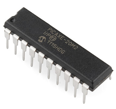
One PICAXE 20M2 to control which direction to spin the motors.
A "strong" 5VDC power source.
-----
Let's take a look at the SN754410NE motor driver IC. First, why is it even required? Motors draw a lot of current. The motors on the OWI Robot measured up to 800mA at full load. That's way too much current to expect from a microcontroller output to drive, so the SN754410NE is required to supply that current. The outputs of the PICAXE 20M2 are programmed to "tell" the SN754410NE motor driver what direction to spin the robot's motors.
Understanding the SN754410NE is simple and straight forward in the configuration we want to use it in. Take a look at the SN754410NE pinout diagram:
One SN74410NE motor driver can control two DC motors to spin in any direction you like; clockwise or counter clockwise. Sure, there are 16 legs on this SN74410NE motor driver chip to wire, but not to worry. If you break it down it is simple. The designers were clever and grouped all the legs for one motor on one side and the legs for other motor on the opposite side. And really, for this application all but four wires on each side are connected to power (+5VDC) or ground. So really, you are only concerned about connecting four "special" connections per motor used. Two will go to the motor and two will go to the PICAXE 20M2 microcontroller.
---
So connecting one motor to the "lower" legs of the SN74410NE motor driver IC will look like this:
See; it's easy. Most legs of the SN74410NE motor driver are connected to +5VDC and ground.
To +5VDC: Legs 1, 16. Legs 8, 9
To GND: Legs 4,5. Legs 12, 13
As for the four "special" connections mentioned above:
Legs 3 and 6 connect to the motor.
Legs 2 and 7 will go the the PICAXE 20M2 microcontroller (more on that later).
Let's point out how the SN74410NE motor driver works:
Condition of Leg 3Condition of Leg 6What does the motor do?
Basically what the table is trying to show is that if Leg 3 and Leg 6 have different voltages the motor will spin. If Leg 3 and Leg 6 have the same voltage the motor will stop. You can "test" this before you connect the PICAXE microcontroller if you like by just connecting the legs straight to the supply voltage and ground. Later, the PICAXE 20M2 will be programmed and connected to control the motor (stay tuned).
But wait, the OWI Edge Robot Arm has five motors and the SN74410NE motor driver can only control two motors. That's no problem if three SN74410NE are used.
----
Below is what the three SN74410NE motor driver ICs look like on a breadboard after the power and grounds are connected. Six motors can be controlled with this set up. Only five motors are needed so we will not connect a motor to the upper side of the right most SN74410NE motor driver.
-----
Let's move from discussing the SN754410NE motor driver IC and switch to controlling how the motors spin control with a custom programmed PICAXE 20M2 microcontroller.
The PICAXE 20M2 is a low cost microcontroller (less than $4) that is easy to program for this application. To control five motors we need 10 outputs; two outputs for each of the five motors. The PICAXE 20M2 has 18 outputs and that is plenty.
-----
Notice how the PICAXE 20M2 legs are labeled; b.7, b.6, etc. The drawing below shows how to wire up the whole system. It shows where to wire power and ground. It shows where wire the motors. It shows where to wire in the PIXACE 20M2 so it will work with the program source code below.
Again, notice nothing is connected to " upper" portion of the SN754410NE motor driver on the far right. Good engineering practice would say the inputs (Leg 10 and Leg 15) should be tied to ground. But, we aren't designing for a Mars rover or anything critical, so everything should be fine. As a general rule leaving inputs floating can lead to a risky design.
The PICAXE 20M2 is programmed (again, example source code below) to control the direction of each motor. From above we know that varying the condition of the SN754410NE motor driver IC inputs has a resulting spin on the motor. The source code for the PICAXE 20M2 simply forces the two SN754410NE motor driver IC inputs high and/or low to make the robot motor spin in the desired direction. High/Low will spin the motor one way. Low/High will spin the motor the other way. The PICAXE 20M2 output conditions are held static in the source code with the PAUSE command to determine how long the motor will spin. If the PICAXE 20M2 is programmed to output High/High or Low/Low the motor will stop moving.
----
Let's wrap this up. These wires connect to the five motors on the OWI robot:
These are the wires that go to straight to the SN754410NE motor driver ICs. If you connect these wires straight to Power and Ground you can document which connector wires control what motor and in what direction.
-----
After you wire the PICAXE 20M2 to the SN754410NE motor driver ICs your breadboard will look something like this:
-----
Add in the wires from OWI Robot motors and your done with the hardware. It will look like this:
-----
Picture of the final build with everything wired in:
-----
A short video demo of all five motors being controlled on the OWI Robot. Be aware that the motors can pull over 500mA each. Running several motors at once can demand a lot of current, so if your design doesn't work suspect the power supply may not have enough output current.
----
A below is source code for the PICAXE 20M2 to make it all work. Basically, the PICAXE 20M2 outputs are set HIGH and/or LOW to control the motors. A PAUSE statement determines how long that motor should stay on. Both outputs LOW stop the motor movement. It is possible to move more than one motor at a time if you have a 5VDC power source that can supply enough current. In the example below all motors are excerised one at a time. The code can be modified to make the OWI Robot dance to your wishes:
What is an "Echo Box" you ask? Simple. You tap on the box and a few seconds later the box echos those taps back to you. The video below shows the rigs operation. Keep reading if you want the build details.
-----
-----
I have programmed a PICAXE 08M microcontroller to monitor for current on a piezo disk. The piezo disk outputs a current when it is struck (or tapped). The PICAXE sample and holds the cadence of the taps with software. If there are no taps for about a second or so the program assumes the tapping is complete and echos the taps back to you on the box.
The piezo sits inside a tube of PVC pipe between two pieces of wine cork that are cut to barely touch the roof of the box. This does a great job of transferring the taps from the top of the box to the piezo input. Here is a picture of the piezo disk resting on top of a wine cork.
-----
And here is the piezo input disk in its final configuration with another piece of wine cork placed on top of it. Basically creating a "piezo sandwich" with wine cork.
-----
Below is how the input from the piezo traces out on the 'scope. A diode in parallel with the piezo protects the PICAXE from getting hit with a negative voltage spike. A 1M resistor also helps to tame the input and make it more predictable.
-----
A DC motor with an offset counter weight spins to shake the box and provide the feedback for the echo.
-----
The circuit perf board is shown below. The red LED is simply there to provide a visual clue that the piezo tap was processed by the PICAXE. It is used only for debug of the project and could be removed. You can also see two 470uF capacitors on the board. Take note that the motor will not get enough instantaneous energy to start without these capacitors. One final note, a transistor as heavy as the 2N6284 is not required, but I had one handy. The more common 2N2222 should be fine.
-----
The rig is powered with 5VDC provided by a rescued Blackberry charger. The headphone jack is not for audio; this jack is used to download the control program into the PICAXE 08M. This jack allows you to easily change the personality of the Echo Box.
-----
The completed Echo Box:
---
-----
Here are two videos of the rig working on the bench.
-----
For those that have hung in there so far with the details, the circuit schematic and code is shown below:
-----
; *******************************
; ***** www.whiskeytangohotel.com *****
; *******************************
; Project Name: Echo Echo
; [with thanks to AndyGadget & the PICAXE Forum]
;
; Start Date: November 15, 2011
; Completed: December 4, 2011
;
; *******************************
#picaxe 08m2
#com 11
'Assign names to pins, variables to registers,and constants.
symbol rnd=w6'Word variable : Current random number
symbol kdel=w5'Word variable : Delay between last and current knock input
symbol cnt1=b0
symbol kcnt=b1'Number of knocks
symbol pptr=b2'Pointer to knock delay storage array
symbol tmp1=b6'Reusable variable
symbol tmp2=b7'Reusable variable
symbol mic=pin2'Microphone input (can also be output)
symbol knock=4'Knock motor output
symbol led=0'Indicator LED for testing
symbol pstart=$50'Start of storage area
symbol tmax =800'Time-out value for delay - About 1.5 seconds
symbol settle=80'Settling time for microphone
'This section is where the person knocks.
'The time between successive knocks is stored
' until there is a pause of 1.5 seconds or so.
do'Start of main loop
kcnt = 0'Initialise knock counter
input 2'Define mic as input to detect knocks
do
for kdel = 1 to tmax'KDel is counting loops to determine time between knocks
if mic = 1 then'Detect HI on microphone input
inc kcnt'Add 1 to number of knocks
high led'Flash LED to help debugging
pause settle'Wait for oscillations to stop
low led
kdel = kdel + settle'Add settle time to loop counter for accuracy
pptr = kcnt * 2 + pstart'KCnnt is a word variable so need to add 2 to pointer
poke pptr,word kdel'Write the delay from last knock to storage area
kdel = 0'Reset kdel ready for next knock
end if
next kdel
loop until kdel >= tmax'If no knocks for over TMax loops then leave loop
'This section will operate sepending on the number of knocks detected.
'If there are no knocks it will exit.
'The maximum number of knocks is 23 to fill buffer. Incorrect count after that.
select case kcnt
case 0'Do nothing if no knocks have occurred
case 21'Put Box in 'Irritate Mode'.
gosub twoknock'gosub twoknow to confirm routine was entered.
wait 10'Do nothing for xx seconds
gosub twoknock
wait 9
gosub twoknock
wait 8
gosub twoknock
wait 7
gosub twoknock
wait 6
gosub twoknock
wait 5
gosub twoknock
wait 4
gosub twoknock
wait 3
gosub twoknock
wait 2
gosub twoknock
wait 1
gosub twoknock
else 'Any other number of knocks will be echoed
for tmp1 = 1 to kcnt'Loop for the number of knocks
pptr = tmp1 * 2 + pstart'Step in twos through buffer
peek pptr,word kdel'Read back delay value words from buffer
pause kdel'Wait the delay time (in milli-seconds)
gosub DoKnock'Perform a knock
next tmp1'Loop for next knock
pause 200
endselect
loop
'This section contains the knocking routines
DoKnock:
high knock'Turn on motor
pause 70'Wait 70 milli-seconds
low knock'Turn off motor
return
TwoKnock:'More compact to do this as subroutine
pause 550'Two knocks with timed delays between for tune
---
The goal was to learn how to program and interface the MSP430 microcontroller with a toy tank and make it drive autonomously in a square after a button is pressed. The project demonstrates simple control of two DC motors (output) and the ability to process a button press (input) with the MSP430. There was no goal to create a pretty robot and I guess I got that done as well. ;)
The material list:
$12.00 toy tank,
$4.30 TI MSP430 LaunchPad,
$2.50 SN754410NE Quad Half H-Bridge
The program is written in C and uploaded into the MSP430 via the Code Composer Studio 4.1 software.
Get your own MSP430 LaunchPad micro controller here for only $4.30.
A few early build pics:
Original Tank (with AirSoft cannon)
---
Here it is five minutes later...
---
The remote control was removed from the tank. The motor wires were hooked straight into the motor driver chip that was controlled by the MSP430 LaunchPad.
---
Below is the source code for the project:
=================
//MSP430 rogram to make tank drive in a square after button push. June 11, 2011
//After the square is complete the tanks waits for a button push to repeat process.
#include msp430g2231.h
void main(void)
{
WDTCTL = WDTPW + WDTHOLD; // Stop watchdog timer
P1DIR |= 0x01; // Set P1.0 to output direction
P1DIR |= 0x40; // Set P1.6 to output direction
volatile long i;
volatile int j;
// RED LED in RIGHT motor. GREEN LED is LEFT motor
P1OUT = 0x41; // Stop motors (both LEDs ON) and
while ((P1IN & 0x08)); // wait for button press on P1.3
for (;;)
{
for (j=1; j<5 data-blogger-escaped-br="br" data-blogger-escaped-j="j">
{
P1OUT = 0x00; // RIGHT and LEFT OFF 'FORWARD'
for (i=0; i<100000 data-blogger-escaped-a="a" data-blogger-escaped-br="br" data-blogger-escaped-delay="delay" data-blogger-escaped-i="i" data-blogger-escaped-little="little">
P1OUT ^= 0x40; // LEFT ON (turn LEFT)
for (i=0; i<20000 data-blogger-escaped-a="a" data-blogger-escaped-br="br" data-blogger-escaped-delay="delay" data-blogger-escaped-i="i" data-blogger-escaped-little="little">
P1OUT =0x00; // Both OFF
for (i=0; i<50000 data-blogger-escaped-a="a" data-blogger-escaped-br="br" data-blogger-escaped-delay="delay" data-blogger-escaped-i="i" data-blogger-escaped-little="little">
} //end J loop
P1OUT =0x41; // Stop motors (both LEDs ON) and
while ((P1IN & 0x08)); // wait for button press