We found this ~60 year old Biddle Megger while going through the closet. It was used by my father's and was no longer working. The fix was possibly something simple, but we don't need a Megger so the crank voltage transformer became more interesting.
-----
Just for the heck of it we decided to mount the crank voltage transformer and discover what it could still do.
We knew based on the dial setting on the Megger that an output of ~1000 Volts AC was possible. To not cook any of our instruments during the test we built 100K:1K Ohm resistive divider to tame the signal. This makes the amplitude of the crank voltage transformer output about 100 times smaller.
Here the results using the Moku:Lab as our measurement tool. This was easy duty for the Moku which has an 13 amazing instruments in one box and worth reading about.
----
Turning the crank as slow as we could yielded about ~480V RMS at 13Hz. Touching the output terminals not was screamingly painful, but we did verify that it is uncomfortable to touch.
----
Max output was ~800V RMS at 55Hz and we wisely decided not to sample the pain level of this output.
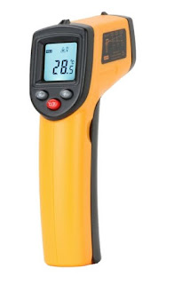
Way back in 2013 we purchased an infrared thermometer from Harbor Freight for less than ten bucks.
All in all the unit performed fine other than the plastic case getting that sticky melting feel that many low cost plastic products can develop over time.
----
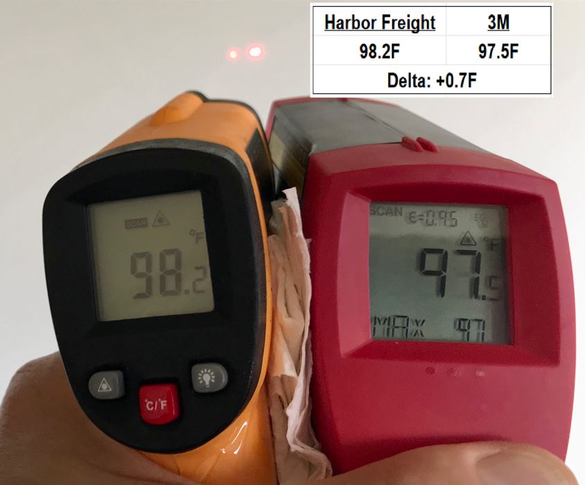
Recently we got our hands on a 3M Model IR-750B "Scotchtrak Heat Tracer" infrared thermometer and decided to compare the two units. Right away it's obvious that the 3M Model IR-750B has a superior feel.
Plus. the 3M Model IR-750B comes in a nice carrying case. We were not able to find pricing on the 3M Model IR-750B, but something tells us the price was more the generic Harbor Freight model. Both units run on a single 9VDC battery.
-----
So..... How do their measurements compare?
-----
Pretty close! Which unit is correct? We don't have a calibrated source so we have no way of knowing. What we do know is they produce temperature readings that are closely collaborated.
It is a pretty commonly uttered question (sometimes loudly) around the home or office; "Is the internet up?" As the go to IT Support Manager around the house this can get a little tiresome. Most of the time the internet is up and it's a user or personal device problem that can be solved with a re-boot, re-load, re-etc. Rarely is the internet really down requiring a router and cable modem reboot or a call to the ISP. Wouldn't a simple visual check that anyone could quickly understand be helpful?
-----
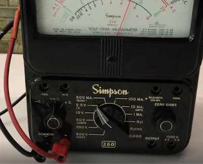
I recently found my father's old Simpson 260 meter. He let me borrow it anytime I wanted with the warning of "DON'T COOK IT!". My memory recalls only using it for continuity and batteries which is good because I did not have a clue as to what would "cook it". I decided to put this heirloom to use as an internet monitor. This project is amazingly useful and simple to duplicate.
-----
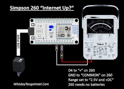
The rig uses an ESP8266 to ping different servers. The ping time (in mS) is displayed on the Simpson 260 and 'percent of full scale'. In other words a ping of 73mS would be 73% of full scale on the Simpson 260. We set the source code (see below) to cycle through ten servers and show the ping result every 15 seconds.
-----
If the LAN is down or a ping error is detected the meter "wags" back and forth 5 times and tries another server. The message to the house is, "If the needle ain't wagging back and forth then your problem ain't with the internet connection!"
-----
Upload the Arduino IDE based source code below to the ESP8266. Connection to the Simpson 260 is easy.
-----
/* * A vintage Simpson 260 meter to shows network PING times * and if there is a connection to the internet. * * Deflect the Simpson meter from 0-100% of the 2.5V full scall * based on ping times of servers. * * 10mS = 10% of full scale. * 45mS = 55% of full scale. * 73mS = 73% if full scale. * XXmS = XX% of full scale, etc.... * Anything over 100ms is consider terrible and just maxes to 100% * * A bad ping (site not found, network down, etc) will 'wag' the meter * back and forth from 0% to 100% five times then try next ping site. * * ESP8266 NodeMCU Board BAUD 115200 * HiLetgo 1PC ESP8266 NodeMCU CP2102 ESP-12E Development Board from Amazon * * Full documetation at: * WhiskyTangoHotel.Com * * FEB2022 * */
#include <ESP8266WiFi.h> #include <Pinger.h>
const char* ssid = "Virus-2.4"; // These vars are your private WIFI const char* password = "zenakelsocats"; // connection information
// Define some 'ping friendly' sites. ARRAY starts a 0 String PingSite[] = { "whiskeytangohotel.com", "google.com", "yahoo.com", "bing.com", "abc.com", "cbs.com", "cnn.com", "apple.com", "pingler.com", "mailinator.com" }; // end ping array define
int Number_of_Ping_Sites = 10; // counted from the list above int Secs_Between_Pings = 15; float Min_Ping_Result = 999; const int PINGOUT = 2; // Drives the S260. Blue onboard LED and ~D4 Pinger pinger;
// For the ping dot h features https://github.com/bluemurder/esp8266-ping pinger.OnEnd([](const PingerResponse& response) { // Print time information if(response.TotalReceivedResponses > 0) { Serial.printf("Approximate round trip times in milli-seconds:\n"); Serial.printf( " Minimum = %lums, Maximum = %lums, Average = %.2fms\n", response.MinResponseTime, response.MaxResponseTime, response.AvgResponseTime); Min_Ping_Result = response.MinResponseTime; }
// Print host data Serial.printf("Destination host data:\n"); Serial.printf( " IP address: %s\n", response.DestIPAddress.toString().c_str()); if(response.DestMacAddress != nullptr) { Serial.printf( " MAC address: " MACSTR "\n", MAC2STR(response.DestMacAddress->addr)); } if(response.DestHostname != "") { Serial.printf( " DNS name: %s\n", response.DestHostname.c_str());
Serial.println("Minimum ping was: " + String(Min_Ping_Result) + "mS." + " Meter to " + String(int(Min_Ping_Result)) + "% of full scale."); Serial.println("Delay to next ping is " + String(Secs_Between_Pings) + " seconds..."); Serial.println("---------------------"); } return true; }); // end ping features
//Self Test the meter by moving the meter full scale // Increase meter value and on board LED brightness for(int dutyCycle = 0; dutyCycle < 200; dutyCycle++){ // changing the LED brightness with PWM; analogWrite(PINGOUT, dutyCycle); Serial.println(String(dutyCycle) + " increasing meter self test..."); //analogWrite(PINGOUT, testval); delay(10); } // end meter increase
// Decrease meter value and on board LED brightness for(int dutyCycle = 200; dutyCycle > 0; dutyCycle--){ // changing the LED brightness with PWM analogWrite(PINGOUT, dutyCycle); Serial.println(String(dutyCycle) + " decreasing meter self test..."); //analogWrite(PINGOUT, testval); delay(10); } // end meter decrease Serial.println("Self test complete!!!"); Serial.println("---------------------");
// Set S260 to +DC. The + lead to D4. Neg lead to GND
void loop() { // loop until the Cowboys win a Super Bowl
for (int i = 0; i <= (Number_of_Ping_Sites - 1); i++) { // don't always use the same PingSite; cycle them. Serial.println("PingSite[" + String(i) + "]: " + PingSite[i]);
if(pinger.Ping(PingSite[i]) == false) { Serial.println("Error during ping command. Walk the meter 5 times."); // Walk the meter back and forth to symbol 'ping error' or network down for (int walk = 0; walk<=4; walk++) { // Increase meter value and on board LED brightness for(int dutyCycle = 0; dutyCycle < 200; dutyCycle++){ // changing the LED brightness with PWM; analogWrite(PINGOUT, dutyCycle); Serial.println(String(dutyCycle) + " Showing FAIL increasing for: " + PingSite[i]); delay(10); } // end fail meter increase
// Decrease meter value and on board LED brightness for(int dutyCycle = 200; dutyCycle > 0; dutyCycle--){ // changing the LED brightness with PWM analogWrite(PINGOUT, dutyCycle); Serial.println(String(dutyCycle) + " Showing FAIL decreasing for: " + PingSite[i]); delay(10); } // end fail meter decrease } // end for fail meter back forth walk } // end if pinger.Ping
// Write Ping value to the meter. Low is better. // We basically make percent of full scale equal the ping in mS, ie; 45mS = 45%... // Anything over a 100mS is a crappy ping so we make 100mS (100% of scale) if (Min_Ping_Result > 100) { Min_Ping_Result = 100; }
analogWrite(PINGOUT, Min_Ping_Result * 2); // move to meter to display the ping value delay(Secs_Between_Pings * 1000); // delay for next ping } // end for/next to cycle the PingSites } // end loop until the Cowboys win the Super Bowl -----
Charging your phone, watch, earbuds, etc. from a wireless charger sometimes doesn't work. Most of the time it is due to poor alignment to the charge point. Of course, it could be that the wireless charger is broken or simply unplugged.
This quick DIY tool helps verify that the charger is plugged in as well as determine the wireless charger's "sweet spot".
-----
-----
The build is about as cheap and simple is it can be. If you have trouble building the rig from the image below you may be following the wrong project site. ;)
We built the Elenco Capacitor Substitution Kit and because it went together so well decided to build it's partner the Elenco Resistor Substitution Kit. Not much else to say; like the Capacitor Substitution Kit the directions are easy to follow for this very basic kit. We did make the same modification and replace the provided alligator clip connection with banana jacks. The measured values look fine:
Not often (okay, almost never) a capacitance substitution box would come in handy on the bench. Finally, the Amazon AI wizard suggested that at $14.99 we couldn't live life any longer without one.
From the pic above you can see that the included wire and alligator clip connector were replaced with banana plug jacks. It gives the rig and the bench a cleaner look.
-----
The directions (which we folded up and placed inside the box for
future generations) were straight forward and the values are accurate
enough per a NIST traceable capacitance meter.
-----
The same company also makes a resistance substitution box which we also don't need, but will probably build up anyway. Both are a nice, cheap, welcome convenience.
Everyone seems to have a box full of USB chargers. Well, we do anyway and decided to pick two random "no name" chargers and pit them up against an official Apple USB charger.
The test setup was the same for each USB charger. We swept a load that increases from 100mA until the USB charger went into protection (no voltage output). We then checked EMI/RF Noise and 'vampire drain'.
EMI/RF Noise is a big concern. EMI/RF can have a negative effect on WiFi, Bluetooth, ham radio, and pretty much any radio signal in the area. Measuring with a Spectrum Analyzer the Apple was by far the most RF quite. The White "no name" was extremely EMI/RF noisy with the Black "no name" being pretty bad as well.
"Vampire drain" or standby power is how much energy the charger uses when just plugged into the wall doing nothing. The Apple won in this category as well.
My opinion, get the Apple or other well made USB charger and avoid the "no
names", The Apple uses less standby power and should not have a negative
effect on your or your neighbors wireless equipment. The Apple power output meets spec as well and is more linear until protection kicks in. The Apple is just better and some "no names" are are just unsafe.
The unit comes complete with a the LED light, rechargeable battery (with a nice nylon case), handle bar mount, and charger.
The light feels solid and well built.
----
So how does it perform? First off; it's bright. Really bright!!! There are three brightness setting, but honestly, the dimmest seems plenty bright. I ran the light from full charge to dead on LOW and HIGH. On LOW a 4.5 hour run time was observed. A Keithley 2110 5 1/2 digit precision digital multimeter was used to record current draw.
-----
The battery pack puts out 8VDC, so don't connect the headlight straight to a 12VDC motorcycle or car battery without spending 60 cents for 7808 regulation.
-----
Current shown by the Keithley 2110 with the unit in STANDBY mode; ~50 hours estimated.
-----
Current shown by the Keithley 2110 with the unit in LOW mode; 4.5 hours observed.
-----
Current shown by the Keithley 2110 with the unit in MEDIUM mode; ~2 hours estimated.
-----
Current shown by the Keithley 2110 with the unit in HIGH mode; 1.5 hours observed.
-----
The unit is built well, works great, and is a fantastic value.

.jpg)