Showing posts with label 3D Printer. Show all posts

Wednesday, June 25, 2025

TCS34725 Color Sensing Cube with Arduino

-----

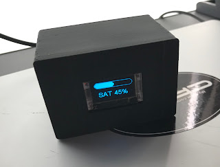
Whatever color the TCS34725 sensor "sees" is reproduced on the orb on top of the cube.   The switch in front is hardwired to the LED light on the front of the sensor because we found the LED annoying and most of the time unnecessary.

-----

Bill of Materials....

     TCS34725

     The orb is a plastic cover from a non functioning LED light bulb: 

     An old Arduino Nano: 
    A switch and a 3D Printed Box:  
-----

Wire per the comments in the Arduino sketch below and you should get this:


-----

// Read Color Sensor.  Mimic color on RGB LED sees
// https://www.whiskeytangohotel.com/
// JUNE 2026

// Arduino Nano but, must selected under Tools → Processor:
// ATmega328P (Old Bootloader) or suffer the avrdude error.

#include <Wire.h>
#include "Adafruit_TCS34725.h"

// TCS34725 SDA pin should be connected to A4
// TCS34725 SCL pin should be connected to A5
// TCS34725 GND to GND
// TCS34725 3.3V to 5V (Vin is No Connect)
// TCS34725 LED goes to hardwired switch  

// Define pins for RGB LED
const int RED_PIN = 10;
const int GREEN_PIN = 9;
const int BLUE_PIN = 11;

// Define digital pin for TCS34725 LED control
const int SENSOR_LED_PIN = 6;  // Not used, this LED is controlled with a hardwired switch

// Initialize the sensor
Adafruit_TCS34725 tcs = Adafruit_TCS34725(
  TCS34725_INTEGRATIONTIME_50MS,
  TCS34725_GAIN_4X
);

void setup() {
  Serial.begin(9600);  // We use the serial monitor for debug
  
  // RGB LED pins
  pinMode(RED_PIN, OUTPUT);
  pinMode(GREEN_PIN, OUTPUT);
  pinMode(BLUE_PIN, OUTPUT);

  // Sensor LED control pin
  pinMode(SENSOR_LED_PIN, OUTPUT);
  digitalWrite(SENSOR_LED_PIN, LOW); // turn off sensor LED initially

  if (tcs.begin()) {
    Serial.println("TCS34725 sensor found");
    // Self-test only if sensor found: cycle RGB LED through R, G, B 
    for (int i = 7; i > 0; i--) {
      // Red
      Serial.println("RED Self Test");
      analogWrite(RED_PIN, 255);
      analogWrite(GREEN_PIN, 0);
      analogWrite(BLUE_PIN, 0);
      delay(50 * i);

      // Green
      Serial.println("GREEN Self Test");
      analogWrite(RED_PIN, 0);
      analogWrite(GREEN_PIN, 255);
      analogWrite(BLUE_PIN, 0);
      delay(50 * i);

      // Blue
      Serial.println("BLUE Self Test");
      analogWrite(RED_PIN, 0);
      analogWrite(GREEN_PIN, 0);
      analogWrite(BLUE_PIN, 255);
      delay(50 * i);  
    }  
  } else {
    Serial.println("No TCS34725 sensor found ... check wiring?");
    // RED LED to show error
    analogWrite(RED_PIN, 155);
    analogWrite(GREEN_PIN, 0);
    analogWrite(BLUE_PIN, 0);
    while (1);
  }
}

void loop() {
  uint16_t r, g, b, c;
  tcs.getRawData(&r, &g, &b, &c);

  if (c < 5) {
    // In near total darkness: cycle through rainbow
    showRainbowCycle();
  } else {
    // Normal color mimic
    uint16_t maxRaw = max(max(r, g), b);
    if (maxRaw == 0) maxRaw = 1;

    int redVal   = (uint32_t)r * 255 / maxRaw;
    int greenVal = (uint32_t)g * 255 / maxRaw;
    int blueVal  = (uint32_t)b * 255 / maxRaw;

    redVal   = constrain(redVal, 0, 255);
    greenVal = constrain(greenVal, 0, 255);
    blueVal  = constrain(blueVal, 0, 255);

    analogWrite(RED_PIN,   gammaCorrect(redVal));
    analogWrite(GREEN_PIN, gammaCorrect(greenVal));
    analogWrite(BLUE_PIN,  gammaCorrect(blueVal));
  }

  delay(50); // smooth update
}


int gammaCorrect(int val) {  // makes it look "better"
  float gamma = 2.2;
  return pow(val / 255.0, gamma) * 255.0;
}

void showRainbowCycle() {  // If full dark gentle cycle thru colors
  static float hue = 0;
  hue += 0.5;  // Change speed here
  if (hue > 360) hue = 0;

  float r, g, b;
  float s = 1.0;
  float v = 1.0;
  float h = hue;

  int i = int(h / 60.0) % 6;
  float f = h / 60.0 - i;
  float p = v * (1 - s);
  float q = v * (1 - f * s);
  float t = v * (1 - (1 - f) * s);

  switch(i) {
    case 0: r = v, g = t, b = p; break;
    case 1: r = q, g = v, b = p; break;
    case 2: r = p, g = v, b = t; break;
    case 3: r = p, g = q, b = v; break;
    case 4: r = t, g = p, b = v; break;
    case 5: r = v, g = p, b = q; break;
  }

  analogWrite(RED_PIN,   gammaCorrect(int(r * 255)));
  analogWrite(GREEN_PIN, gammaCorrect(int(g * 255)));
  analogWrite(BLUE_PIN,  gammaCorrect(int(b * 255)));
}
-----

Saturday, December 23, 2023

Make Your Own Tombstone and SAVE!


-----

We saw this Hackaday article where [Proper DIY] used his woodworking skills to produce some excellent quality concrete signs and decorations.   We liked the idea but the effort required fashioning the wood for the letters seemed like a lot of work to us.

-----

So.... we have a 3D printer and set out to find an easier way.   The 'recipe' is pretty easy:

    1)Print your design on a 3D printer.     2)Glue the design to the bottom of a concrete mold.     3)Pour concrete, shake out the bubbles, and wait for curing.     4)Unscrew the mold and release the final product.

The results are good enough with only a fraction of the time (and skill).  

-----

Maybe not needed, but here is a little more detail:

- Build mold (use long wood screws to allow reuse):

- Print your 3D design and glue it the the bottom of the mold:


- Fill the mold, vibrate out the voids, then wait.  We used this material mainly because we had some on hand:

- Results:


-----

We are happy with outcome.  [Proper DIY] did have better results, but with a whole, whole, whole lot more effort.

-----

Monday, February 7, 2022

Retirement Clock Goes Digital


-----

We overheard in a conversation recently something like: "Now that I'm retired I really only focus on what day of the week it is and the general time of day."  We then discovered this awful looking Day of the Week Clock and the vision of a more modern version came to mind.

-----

The rig is based around this MakerFocus ESP32 Development Board mainly because it works with the Arduino IDE and has WiFi with a display on board.   The code (source below) gets it's time/date from a NTP server and then simply figures out and displays the day of the week and what percentage of the day has past.  Evidently this is all the critical information needed to guide the non-working through their day.

-----

To dress up the look a case was 3D printed.  After seeing the result we needed to celebrate with a beer.   As shown in the video below it was a bit early in the day for a drink, but as the ol' saying goes "It's 71% somewhere!".

-----

Retirement Clock Source Code:

/*
 * HelTec Automation(TM) ESP32 Series Dev boards OLED "Retirement Clock"
 * Adruino IDE Board Setting: WiFi Kit32, Disabled, 240MHz, 921600, None
 *
 * "Retirement Clock" shows only Day of Week and percentage time left in the day.
 *  
 * FEB 2022
 * Search whiskeytangohotel.com for project details.
 *
*/

#include "Arduino.h"
#include "heltec.h"

#include <TimeLib.h>
#include <WiFi.h>
#include <WiFiUdp.h>

const char ssid[] = "xxxxxxx";  //  your network SSID (name)
const char pass[] = "xxxxxxx";       // your network password
long Sync_Delay = 60000;  //  60000 is sync every ten minutes,  We aren't going for precision here. LOL

int DOWNUM = 0;     //  DOWNUM from NTP (expect 0 - 6)
String DOW = "DOW";  // DOWNUM to a Day of Week String
int hourNUM = 0;    //  hour() value from NTP
float minuteNUM = 0;   // minute() value from NPT

// NTP Servers:
static const char ntpServerName[] = "pool.ntp.org";
const int timeZone = 0;     // leave as 0 for UTC.  We do the offset math in void setup

WiFiUDP Udp;
unsigned int localPort = 8888;  // local port to listen for UDP packets

time_t getNtpTime();
void digitalClockDisplay();
void printDigits(int digits);
void sendNTPpacket(IPAddress &address);

void setup() {
  //NTP setup
  Serial.begin(115200);
  while (!Serial) ; // Needed for Leonardo only
  delay(250);
  Serial.println("TimeNTP");
  Serial.print("Connecting to... ");
  Serial.println(ssid);
  WiFi.disconnect();
  WiFi.mode(WIFI_MODE_STA);
  WiFi.begin(ssid, pass);

  while (WiFi.status() != WL_CONNECTED) {
    delay(500);
    Serial.print(".");
  }

  Serial.print("IP number assigned by DHCP is: ");
  Serial.println(WiFi.localIP());
  Serial.println("Starting UDP");
  Udp.begin(localPort);
  Serial.print("Local port: ");
//  Serial.println(Udp.localPort());
  Serial.println("waiting for sync... ");
  setSyncProvider(getNtpTime);
  setSyncInterval(Sync_Delay);  //   defines how often to check NTP time

  // Hetec setup
  Heltec.begin(true /*DisplayEnable Enable*/, false /*LoRa Disable*/, true /*Serial Enable*/);
  Heltec.display->flipScreenVertically();
  Heltec.display->setFont(ArialMT_Plain_24);
} // end setup link

time_t prevDisplay = 0; // when the digital clock was last displayed timer

void loop() {   // main program loop
  if (timeStatus() != timeNotSet) {
    if (now() != prevDisplay) { //update the display only if time has changed
      prevDisplay = now();
    }
  }

  // Parse time info and send info to serial monitor (for debug)
  Serial.print(hour());
  printDigits(minute());
  printDigits(second());
  Serial.print(" ");
  Serial.print(day());
  Serial.print(".");
  Serial.print(month());
  Serial.print(".");
  Serial.print(year());
  Serial.print(" : ");

  if (int(year()) < 2022) {
     Serial.print(String(int(year())) + " is the NTP server year.  That aint right, so try again!!!");
     Serial.println();      
     setup();
  }   // the NTP server return something 'wierd' (probably 1970) so try again  

  //Covert Time in percent of day completed.  Midnight Local = 0%, Noon Local = 50%  
  minuteNUM = minute();
  hourNUM =   int(hour());  
  // manually adjust hourNUM and minuteNUM for debug
  // hourNUM =  5;    // valid values are INTERGERS 0 thru 24
  // minuteNUM = 49;    // valid values are INTEGERS 0 thru 60  

  minuteNUM = minuteNUM / 60;    // covert minutes to 'fraction'  
  hourNUM = hourNUM - 6;   // hourNUM is in UTC.   Adjust to local.   -6 = CST, -5 = CDT, 0 = UTC
  DOWNUM = int(weekday());
   
  // Calculate percentage of the day pasted into 'progress'
  int progress = round(   (  ((hourNUM + minuteNUM))   /  24   )  * 100    );
  if (progress < 0) {   // it's past UTC midnight and the timezone offset created a negative %
    progress = 100 + progress;
    DOWNUM = DOWNUM -  1;
  }  //end progress < 0

  // Convert DOWNUM into printable String.  Sunday is 1
  if (DOWNUM  == 1) { DOW = "SUN"; }
  if (DOWNUM  == 2) { DOW = "MON"; }
  if (DOWNUM  == 3) { DOW = "TUE"; }
  if (DOWNUM  == 4) { DOW = "WED"; }
  if (DOWNUM  == 5) { DOW = "THU"; }
  if (DOWNUM  == 6) { DOW = "FRI"; }
  if (DOWNUM  == 7) { DOW = "SAT"; }

  Serial.print(String(int(weekday())) + " is " + DOW);
  Serial.println();   
  Serial.print(String(hourNUM) + " + " + String(minuteNUM) + " = " + String(progress) + "%");
  Serial.println();
 
  // clear the display
  Heltec.display->clear();

  // Draw the Precent of Day pasted onto progress bar
  Heltec.display->drawProgressBar(0, 0, 127, 20, progress);

  // Label the Day Of Week and percentage as String
  Heltec.display->setTextAlignment(TEXT_ALIGN_CENTER);
  Heltec.display->drawString(60, 31, DOW + " " + String(progress) + "%");
  // Write buffer to Heltec display
  Heltec.display->display();
 
  delay(5000); // wait some.  we are in no hurry to update the screen
}  // end void loop main program


void printDigits(int digits)
{
  // utility for digital clock display: prints preceding colon and leading 0
  Serial.print(":");
  if (digits < 10)
    Serial.print('0');
  Serial.print(digits);
}

/*-------- NTP code ----------*/

const int NTP_PACKET_SIZE = 48; // NTP time is in the first 48 bytes of message
byte packetBuffer[NTP_PACKET_SIZE]; //buffer to hold incoming & outgoing packets

time_t getNtpTime()
{
  IPAddress ntpServerIP; // NTP server's ip address

  while (Udp.parsePacket() > 0) ; // discard any previously received packets
  Serial.println("Transmit NTP Request");
  // get a random server from the pool
  WiFi.hostByName(ntpServerName, ntpServerIP);
  Serial.print(ntpServerName);
  Serial.print(": ");
  Serial.println(ntpServerIP);
  sendNTPpacket(ntpServerIP);
  uint32_t beginWait = millis();
  while (millis() - beginWait < 1500) {
    int size = Udp.parsePacket();
    if (size >= NTP_PACKET_SIZE) {
      Serial.println("Receive NTP Response");
      Udp.read(packetBuffer, NTP_PACKET_SIZE);  // read packet into the buffer
      unsigned long secsSince1900;
      // convert four bytes starting at location 40 to a long integer
      secsSince1900 =  (unsigned long)packetBuffer[40] << 24;
      secsSince1900 |= (unsigned long)packetBuffer[41] << 16;
      secsSince1900 |= (unsigned long)packetBuffer[42] << 8;
      secsSince1900 |= (unsigned long)packetBuffer[43];
      return secsSince1900 - 2208988800UL + timeZone * SECS_PER_HOUR;
    }
  }
  Serial.println("No NTP Response :-(");
  return 0; // return 0 if unable to get the time
}

// send an NTP request to the time server at the given address
void sendNTPpacket(IPAddress &address)
{
  // set all bytes in the buffer to 0
  memset(packetBuffer, 0, NTP_PACKET_SIZE);
  // Initialize values needed to form NTP request
  // (see URL above for details on the packets)
  packetBuffer[0] = 0b11100011;   // LI, Version, Mode
  packetBuffer[1] = 0;     // Stratum, or type of clock
  packetBuffer[2] = 6;     // Polling Interval
  packetBuffer[3] = 0xEC;  // Peer Clock Precision
  // 8 bytes of zero for Root Delay & Root Dispersion
  packetBuffer[12] = 49;
  packetBuffer[13] = 0x4E;
  packetBuffer[14] = 49;
  packetBuffer[15] = 52;
  // all NTP fields have been given values, now
  // you can send a packet requesting a timestamp:
  Udp.beginPacket(address, 123); //NTP requests are to port 123
  Udp.write(packetBuffer, NTP_PACKET_SIZE);
  Udp.endPacket();
}

-----

Saturday, November 28, 2020

Ham Radio Fox Hunt Attenuator [FAIL]


-----

One of the many aspects of the ham radio hobby is finding a hidden transmitter; also called a fox hunt.  These are often set up by local clubs as a fun social activity, but they can also be competitive athletic events.  We had done a few fox hunts for fun, but were unsuccessful in finding the transmitter.  What we learned is when you get close to a transmitter (regardless of the power it is outputting) the signal becomes so strong there is no way to reliably get the direction information needed to track it down.   It's basically like a bright light blinding you and sunglasses are needed to reduce the input getting into your eyes.  To reduce the radio frequency (RF) signals picked up by your receiver (from the fox) an attenuator is used. 

-----

We saw this HMC472 Digital RF Attenuator Module on sale for $10US and thought it would be a cheap and simple project to solve our fox hunt problems.  We were wrong.....

It's not the module's fault; it works as spec'd.  Here are our measurement results from the bench:

-----
Wow, ten bucks buys a lot!   So....   what's the issue?  Well, after 3D printing a box for the rig we took it out into the field for a test drive and learned that 32dB attenuation is not nearly enough.   You need at least 100dB from what we later discovered.   Still, the final product came out nice, it did work as advertised, and things were learned.  We're gonna call that a win.  We could cascade a few modules to get more attenuation, but there are better solutions.  Here are some details on the simple build:
 
-----

Wednesday, July 29, 2020

3D Printed FlexRadio Maestro Stand

-----
The stand for the FlexRadio Maestro is bulky and doesn't travel well.   FlexRadio does make folding feet to take care of this, but that solution is a hundred bucks.  We didn't need a less bulky travel stand all the time and we didn't want to part with the cash.  So.... we printed one.
-----
Works great!  Design file on Thingiverse.

-----

Sunday, July 19, 2020

3D Printed Single Lever Paddle/Cootie Morse Code Key


-----
We had originally printed this Morse Code key to operate in "Cootie" mode.  You can read about that here.   It turns out using a Cootie key is fun and easy on the wrist, but.....  learning to operate a Cootie key does take some practice.   That said, the automotive spark plug feeler gauge gave such an effortless feel we decided to make a small modification and create a Single Lever Paddle from the original design.
-----
This mod allows usage with an electronic keyer in three terminal mode.  The two terminals on the left can be shorted to quickly switch into Cootie mode.

Hardware parts list:

-----


-----

Monday, April 13, 2020

3D Printed "Cootie" Key for CW/Morse Code

-----
May 2020 Update:  This key was gifted to KK5PJ who was extremely patient with me in my very first CW QSO and the many practice sessions that followed.  THX.
-----
CW or Morse Code is a way ham radio operators send messages with a simple tone of two durations.  It was a must before the days of wireless voice communications and still remains popular because it is a fun challenge.  Also, due to its efficiency messages can get through with limited power or in poor conditions.
-----
There are no shortage of morse code key designs, but in general they fall into a few categories that are discussed here.  We decided to DIY a "cootie" or "sideswiper" key and used our 3D printer to produce this design from Thingiverse.

Hardware parts list:

-----
The result was surprisingly fantastic in both look and feel.   Now, to practice.

-----

Sunday, March 15, 2020

Icom IC7300: Memory External Keypad


-----
The Icom IC7300 is a fantastic and very popular ham radio HF rig.  One thing that we didn't care for is if you utilize the transmit memory functions for CW, phone, etc. half of the touch screen was dedicated to the memory location buttons.
The IC7300 has other features that are a much better use of the touch screen real estate than displaying the memory location buttons.  A few examples are...

Making the Band Scope larger:

Displaying the Audio Scope:

Or getting more information on how the rig is behaving:
-----
In a RTFM moment, I discovered that Icom had a simple circuit that allows the operator to use an external switch keypad to control the top four memory locations. 

-----
A search of our spare parts bin uncovered that all of the materials needed were "in stock".  We set the 3D printer on a mission to print a project box while the soldering iron connected everything up.   Soldering took about 10 minutes; the 3D print a few hours.  The end result is a nicely done external keypad for the memories.   We like it; we like it a lot!

The project is cheap, easy, and useful.  73!

-----

Sunday, April 21, 2019

CW Key via USB Port for RemoteHam.Com Operation


-----
Note:  As presented this project requires a FCC Amateur Radio license.  Amateur Radio is about experimentation.   Even still you must be versed in the band plan, stay away from local repeater stations, stay in accordance to FCC Amateur Radio rules in FCC Section 97, and probably a few other things.  Also, you will be a guest on a remote ham radio station owned by someone that is nice enough to let you enjoy their (often very impressive) rig.  Adhere to the guidelines they post when you log into their station.  It's their station; they make the rules.  Be a good guest and everyone has fun!  That said, let's continue....
-----
We have been wanting to experiment with remote ham radio operation for awhile now.  This weekend band conditions were poor so I was dreaming of having a more expensive and better amp/antenna setup.  This was a great excuse to give RemoteHams.Com a try.  After signing up and installing the Remote Client software I was presented with 100s of rigs to choose from all over the World.  I was amazed.
-----
I somewhat randomly selected the rig of N4GYN.  This was great because I was greeted by Ray and after a brief online chat he verified my license and gave me permission to transmit!
-----
Ray's station lets you operate phone using a headset plugged into your PC's USB port.  The headset part for phone is easy; most any USB headset will do.  However, we only had an interest in operating CW (Morse code).  Ray's rig lets you do that from your PC keyboard by just typing in what you wanted to send.  But, we wanted to use a traditional key.
-----
Here's how we did it:  You can set this up for paddle or straight key operation.  Since we had a cheap straight key not being used we went with that.  What you see in the image at the top of the page is the straight key wired into a USB to RS232 serial port adapter like so:

with the Remote Rig setting as:


-----
On our very first CQ we had our very first remote station manual CW key QSO with NA5N who was 3W QRP from Colorado!!!  If you are wishing you had a better station or you have QTH restrictions consider giving RemoteHams.Com a try.
-----
73!