Showing posts with label switch. Show all posts

Wednesday, June 25, 2025

TCS34725 Color Sensing Cube with Arduino

-----

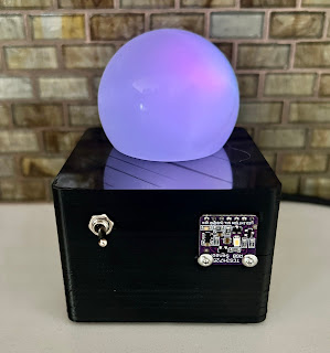
Whatever color the TCS34725 sensor "sees" is reproduced on the orb on top of the cube.   The switch in front is hardwired to the LED light on the front of the sensor because we found the LED annoying and most of the times unnecessary.

-----

Bill of Materials....

     TCS34725

     The orb is a plastic cover from a non functioning LED light bulb: 

     An old Arduino Nano: 
    A switch and a 3D Printed Box:  
-----

Wire per the comments in the Arduino sketch below and you should get this:


-----

// Read Color Sensor.  Mimic color on RGB LED sees
// https://www.whiskeytangohotel.com/
// JUNE 2026

// Arduino Nano but, must selected under Tools → Processor:
// ATmega328P (Old Bootloader) or suffer the avrdude error.

#include <Wire.h>
#include "Adafruit_TCS34725.h"

// TCS34725 SDA pin should be connected to A4
// TCS34725 SCL pin should be connected to A5
// TCS34725 GND to GND
// TCS34725 3.3V to 5V (Vin is No Connect)
// TCS34725 LED goes to hardwired switch  

// Define pins for RGB LED
const int RED_PIN = 10;
const int GREEN_PIN = 9;
const int BLUE_PIN = 11;

// Define digital pin for TCS34725 LED control
const int SENSOR_LED_PIN = 6;  // Not used, this LED is controlled with a hardwired switch

// Initialize the sensor
Adafruit_TCS34725 tcs = Adafruit_TCS34725(
  TCS34725_INTEGRATIONTIME_50MS,
  TCS34725_GAIN_4X
);

void setup() {
  Serial.begin(9600);  // We use the serial monitor for debug
  
  // RGB LED pins
  pinMode(RED_PIN, OUTPUT);
  pinMode(GREEN_PIN, OUTPUT);
  pinMode(BLUE_PIN, OUTPUT);

  // Sensor LED control pin
  pinMode(SENSOR_LED_PIN, OUTPUT);
  digitalWrite(SENSOR_LED_PIN, LOW); // turn off sensor LED initially

  if (tcs.begin()) {
    Serial.println("TCS34725 sensor found");
    // Self-test only if sensor found: cycle RGB LED through R, G, B 
    for (int i = 7; i > 0; i--) {
      // Red
      Serial.println("RED Self Test");
      analogWrite(RED_PIN, 255);
      analogWrite(GREEN_PIN, 0);
      analogWrite(BLUE_PIN, 0);
      delay(50 * i);

      // Green
      Serial.println("GREEN Self Test");
      analogWrite(RED_PIN, 0);
      analogWrite(GREEN_PIN, 255);
      analogWrite(BLUE_PIN, 0);
      delay(50 * i);

      // Blue
      Serial.println("BLUE Self Test");
      analogWrite(RED_PIN, 0);
      analogWrite(GREEN_PIN, 0);
      analogWrite(BLUE_PIN, 255);
      delay(50 * i);  
    }  
  } else {
    Serial.println("No TCS34725 sensor found ... check wiring?");
    // RED LED to show error
    analogWrite(RED_PIN, 155);
    analogWrite(GREEN_PIN, 0);
    analogWrite(BLUE_PIN, 0);
    while (1);
  }
}

void loop() {
  uint16_t r, g, b, c;
  tcs.getRawData(&r, &g, &b, &c);

  if (c < 5) {
    // In near total darkness: cycle through rainbow
    showRainbowCycle();
  } else {
    // Normal color mimic
    uint16_t maxRaw = max(max(r, g), b);
    if (maxRaw == 0) maxRaw = 1;

    int redVal   = (uint32_t)r * 255 / maxRaw;
    int greenVal = (uint32_t)g * 255 / maxRaw;
    int blueVal  = (uint32_t)b * 255 / maxRaw;

    redVal   = constrain(redVal, 0, 255);
    greenVal = constrain(greenVal, 0, 255);
    blueVal  = constrain(blueVal, 0, 255);

    analogWrite(RED_PIN,   gammaCorrect(redVal));
    analogWrite(GREEN_PIN, gammaCorrect(greenVal));
    analogWrite(BLUE_PIN,  gammaCorrect(blueVal));
  }

  delay(50); // smooth update
}


int gammaCorrect(int val) {  // makes it look "better"
  float gamma = 2.2;
  return pow(val / 255.0, gamma) * 255.0;
}

void showRainbowCycle() {  // If full dark gentle cycle thru colors
  static float hue = 0;
  hue += 0.5;  // Change speed here
  if (hue > 360) hue = 0;

  float r, g, b;
  float s = 1.0;
  float v = 1.0;
  float h = hue;

  int i = int(h / 60.0) % 6;
  float f = h / 60.0 - i;
  float p = v * (1 - s);
  float q = v * (1 - f * s);
  float t = v * (1 - (1 - f) * s);

  switch(i) {
    case 0: r = v, g = t, b = p; break;
    case 1: r = q, g = v, b = p; break;
    case 2: r = p, g = v, b = t; break;
    case 3: r = p, g = q, b = v; break;
    case 4: r = t, g = p, b = v; break;
    case 5: r = v, g = p, b = q; break;
  }

  analogWrite(RED_PIN,   gammaCorrect(int(r * 255)));
  analogWrite(GREEN_PIN, gammaCorrect(int(g * 255)));
  analogWrite(BLUE_PIN,  gammaCorrect(int(b * 255)));
}
-----

Monday, February 25, 2019

Ham Radio: Home Brew Fox Transmitter

 
-----
Note:  As presented this project requires a FCC Amateur Radio license.  Amateur Radio is about experimentation.   Even still you must be versed in the band plan, stay away from local repeater stations, stay in accordance to FCC Amateur Radio rules in FCC Section 97, and probably a few other things.  Even after following all those rules, nobody likes to hear a fox 'screaming' out all the time.  Be courteous, aware of your RF footprint, and keep your transmission power suitable for the cause.  That said, let's continue....

In ham radio speak a fox hunt is a search for a hidden transmitter. We wanted a fox transmitter and decided to go with the "roll your own method" to fill the need.
-----
For our rig we went with things that we had available around the shack.  The major components:
     - Baofeng 2m/70cm HT
               - this is the transmitter
     - Arduino Nano
               - used as a simple timer to control a relay module
     - Relay Module
               - when closed the mic keys and the radio transmits
     - MP3 playback device capable of a continuous loop of an audio file
               - this contains the fox message with must include an FCC callsign
     - Some 1/4 inch phono adapters
     - Alligator clip wire
-----
 Since we don't need a permanent fox, we wanted to be able to break down the rig.  Thus, the alligator clip wire.  On low power transmit the rig's battery can easily last all day.  The Arduino and MP3 player are powered by a USB jump battery.
-----
1st:  Get the simple source code we list below and upload it to your Arduino.

2nd: Create a 'fox message' to transmit from the MP3 player.  We typically go to LCWO and create a CW message like the example in the demonstration video at the top of this page.  You must ID with a FCC callsign.

3rd: Connect it all up like this:


 -----
Now you're ready to go.    The metal lanyard attachment point provides a handy "GND" point for the transmit relay.  Select the audio file you want to transmit to continuously loop and press PLAY.  Turn the HT on and power up the Arduino.
-----
At power up the Arduino will go through a Self Test.  The relay will cycle five times and then normal operation will start.  The Fox will only transmit when the relay is closed.  In the source code below the rig is set up to transmit for 20 seconds, then rest for 60 seconds, then repeat.
-----
Pretty simple.  Good luck and enjoy hosting a fox hunt.   Here is the Arduino source code:

/*
 *  Ham Radio Fox Transmitter Control
 *  Requires a ham radio license. 
 *  See: http://www.arrl.org/getting-licensed
 * 
 *  For our Nano: CH340 drivers, Processor->ATmega328P (Old Bootloader), 57600 baud
 * 
 *  See: WhiskeyTangoHotel.Com for built details.
 * 
 *  FEB 2019
 */

// Set variables and Output pins
const int Tx_seconds = 20;   // seconds that the fox call will be sent
const long Silent_seconds = 60; // seconds between fox call tx.  Resting time.
const long test_chatter = 5; // turn on and off the relay for self test.  This will key the mic and Tx if connected
const int relay = 2;  // Relay control line.  Close relay to transmit

void setup(void){  //run once
  pinMode(relay, OUTPUT);
  digitalWrite(relay, 0);  // off power to relay (not in Tx mode)
 
  // Self test LED and Relay
  Serial.begin(57600);
  Serial.println("Enter Self Test:");
  for (int i=0; i < test_chatter; i++){
    Serial.println("*** Self Test: " + String(i) + " ***");
    Serial.println("Tx Mode ON. LED ON.  Relay CLOSED.");
    digitalWrite(relay, 1);  // Relay CLOSED
    delay(500);
   
    Serial.println("Tx Mode OFF. LED OFF.  Relay OPEN.");
    digitalWrite(relay, 0);  // Relay CLOSED
    delay(500);
    Serial.println(" ");
  }

  Serial.println("Self Test complete. Tx is OFF....");
  Serial.println(" ");
  delay(5000);
 
} // end void setup

void loop(void){   // loop until killed by sunspot overdose
  // Turn on the Fox Transmitter
  digitalWrite(relay, 1);  // Relay CLOSED

  Serial.println("Tx is ON for " + String(Tx_seconds) + " seconds...");
  delay(Tx_seconds * 1000); // Keep the Tx mode active

  //Turn off the Fox Transmitter
  digitalWrite(relay, 0);  // Relay OPEN

  Serial.println("Tx is OFF for " + String(Silent_seconds) + " seconds...");
  delay(Silent_seconds * 1000);  //  wait for next Fox Tx
 
} // end main void loop
-----

Tuesday, August 16, 2011