
-----
UPDATE July 4, 2016:
No longer for sale. Get the source code for free by sending a request with your City/State/Country (only so we can pin our map) to:
 In addition to the V-Strom; the GPI is now working on several Suzuki motorcycles!!! Thanks go out to the many dozens of brave DIY'ers that have successfully built and installed the rig proving that the instructions are complete and the design solid. If your rig is not working double/triple check your wiring.
No longer for sale. Get the source code for free by sending a request with your City/State/Country (only so we can pin our map) to:
-----
The objective was to provide a low cost gear position and ambient air temperature display for my 2009 Suzuki V-Strom (DL1000). Also, to open source the project design with documentation so that anyone with basic electronic skills can duplicate the design for their motorcycle.
-----
Theory of Operation:
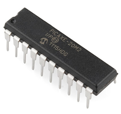
Most modern motorcycles have a Gear Position Indicator (GPI) signal wire from/to the Engine Control Module (ECM) that outputs a voltage reading of 0 to 5VDC depending on which gear is selected. This project uses a PICAXE 18M2 microcontroller to measure the voltage on that GPI signal wire, process that measurement, and display the selected gear on a 7 segment LED display. At the press of a button, the PICAXE 18M2 reads the ambient air temperature (as measured from a DS18B20 temperature sensor) and displays the reading in Celsius or Fahrenheit on the 7 segment LED display.
A few comments before you do anything....
This is a DIY project. I guarantee nothing other than the project works on my 2009 Suzuki DL1000 and that many (many, many...) others have successfully duplicated the build. If you have done DIY electronic projects you understand that wiring errors, etc. happen and have to be debugged. If you haven't done an electronics DIY project, this build is not that difficult and you should be successful but expect delays as you check your work, decided where you what to mount the components, route wires, etc. Check your work often during your build. Even the very experienced make wiring errors and create solder shorts (among other things). Basically, you are taking on some risk.
With the exception of the PICAXE 18M2 microcontroller, all the components are readily available and cheap. If you have done a few electronics projects you likely have many of the parts already your 'spares' kit. The PICAXE 18M2 microcontroller needs to be loaded with some customized software I wrote to make the project work. I can install this software and ship the programmed PICAXE 18M2 directly to you if you like.
-----
A few answers to common questions:
- Why do I have to get the PICAXE 18M2 from you? Can't I program my own?
- You can write the software and program your own PICAXE if you have a development board. Goto www.picaxe.com to learn more.
- Will it work on my motorcycle?
- Currently the design has been tested on the:
- Suzuki DL1000 V-Strom
- Suzuki DL650 V-Strom
- Suzuki TL1000
- Suzuki Bandit
- Suzuki Hayabusa
- Suzuki Quadracer LT-R450
It should work if you have a late model bike with a Gear Position Indicator (GPI) signal wire. The GPI signal wire puts out a voltage (between 0-5VDC) for each specific gear. The software for the PICAXE 18M2 will likely need minor adjustments for motorcycles not yet tested. I can quickly make these adjustments if you tell me the voltage readings of the GPI wire for each gear (and neutral) of the target motorcycle.
- What's is the most difficult part of duplicating the project?
Avoiding wiring and solder mistakes. Also, after you get the project wired and soldered up, deciding what to mount it in and where to place it on the motorcycle.
-----
Bill of Materials (the PICAXE 18M2):
Before we get into the general bill of materials list, let's talk about getting the PICAXE 18M2:
- the PICAXE 18M2 microcontroller is the "brain" of the project.
- the PICAXE 18M2 can be purchased on the internet for about $7.00; however...
- you must have my software downloaded into the PICAXE for the project to work
- PayPal me and I will mail the programed PICAXE 18M2 to you.
- As of July 4, 2016: No longer for sale. Get our source code for free by sending a request to:
- BE SURE to provide a shipping address.
- BE SURE to provide the make/model info on the target motorcycle for the project.
- If you are designing to a motorcycle not listed, give me the GPI signal wire voltages for each gear and neutral. I will custom program the PICAXE for your bike.
- At this price it should be obvious that the project was not done to make money. I have provided donor hardware/software for well over two decades and like the model.
-----
"All the Other Stuff" Bill of Materials (~$15):
Listed below is The Bill of Materials (B.O.M) for the other components. You can find these components in many places. I like Mouser.Com because their prices are good, they are fast, they have good shipping rates, and they will let you order in single qualities. I have included Mouser.Com part numbers for each item (valid at the time of this writing).
QTY - Description
1 - DIP socket (18 pin) for the PICAXE 18M2
- allows easy removal of the PICAXE 18M2 in the event of a re-program.
- allows you not to solder directly to the PICAXE 18M2 if this concerns you.
- allows you to start the project without the PICAXE 18M2 in hand
- One of many examples is PN#4818-3000-CP from Mouser.Com ($0.20)
1 - Seven segment display with decimal point. Must be Common Anode!!!
- Forward Voltage spec = 1.8-2V
- One of many examples is PN#LDS-HTA514RI from Mouser.Com ($1.09)
- If you don't order LDS-HTA514RI the project will work, but you MUST CONFIRM THE LED SEGMENT PINOUT locations
- If you don't order LDS-HTA514RI the project will work, but you MUST CONFIRM THE LED SEGMENT PINOUT locations
1 - 5 Volt DC Regulator
- PN#926-LM2940T-5.0/NOPB from Mouser.Com ($1.68)
- LM7805 could also work if you already have one handy
1 - .47uF capacitor for voltage regulator input on the LM2940T-5.0
- any current rating or tolerance is fine
- One of many examples is PN#UFW2AR47MDD from Mouser.Com ($0.08)
1 - 22uF capacitor for voltage regulator output in the LM2940T-5.0
- any current rating or tolerance is fine
- One of many examples is PN#REA220M1CBK-511P from Mouser.Com ($0.06)
1 - Temperature Sensor (optional, but does not make the project more difficult)
- PN#700-DS18B20+ from Mouser.Com ($2.76)
1 - Push button switch (optional for temperature, but does not make the project more difficult)
- any current or voltage rating is fine
- One of many examples is PN#104-0013-EVX from Mouser.Com ($0.91)
1 - 4.7K resistor for DS18B20+ temperature sensor (optional for temperature)
- any current rating or tolerance is fine
- One of many examples is PN#299-4.7K-RC from Mouser.Com ($0.10 each)
8 - 330R current limiting resistors for the gear readout display
- any current rating or tolerance is fine
- One of many examples is PN#299-330-RC from Mouser.Com ($0.10 each)
2 - 10K pull down resistor for temperature button switch and PICAXE (not optional)
- any current rating or tolerance is fine
- One of many examples is PN#299-10K-RC from Mouser.Com ($0.10 each)
2 - 22K pull down resistor for PICAXE
- any current rating or tolerance is fine
- One of many examples is PN#299-22K-RC from Mouser.Com ($0.10 each)
1 - PCB "perf" board to attach the parts to
- Many examples are available. Select one that aligns the design of your final packaging
- One of many examples is PN#854-SB300 from Mouser.Com ($3.99)
- some 22 gauge solid core hook up wire, solder, mounting 'box', and electronics DIY know how...
-----
After you get your parts, connect them as shown in the schematic below. You may not (or may) want to mimic by component placement as shown in the picture above. A common adjustment is to use longer wires to connect the 7 Segment Display to the PICAXE 18M2. That is fine and may give a cleaner look because the 7 Segment Display could be remoted and would be the only thing visible to the rider; the other circuity could be hidden. I'm sure there are many other packaging considerations.
Check your work often with an ohm meter to verify your connections and that there are no accidental shorts created in the solder process. It is a lot harder to debug an error if you wait until the end; sometimes seemingly impossible...
(click the schematic to make it larger)

-----
Now that you have the components installed and soldered down it is time to connect the unit to the bike. But first, be patient... Let's check a few things:
- Apply 12VDC power the the unit. Take note of + and GND; don't hook it up backwards!!! The unit should go through a "Count Up/Count Down" Self Test followed by displaying the temperature (in C or F; whichever you asked for).
- Then the unit will try to display the current gear. Since the unit is not connected to the bike this number will not mean anything. The number may jump around some as well. That's normal right now.
-----
Now... To the bike:
On the 2009 Suzuki DL1000 you are looking for a PINK wire on the ECM; that is the GPI signal wire. I simply unplugged the ECM connector located behind my battery to find it. This is the GPI signal wire and may not be PINK on other motorcycles. See pic below:

-----
We want to connect leg 18 on the PICAXE 18M2 to this PINK wire. Many ways to do this, but in the pic below you can see I removed a small piece of insulation, wrapped the wire from leg 18 on the PICAXE 18M2 around it. I then soldered it on for a solid, reliable connection.

-----
Congratulations. After connecting those three wires (12VDC, Ground, GPI signal wire) to your motorcycle you will now have a working digital gear position indicator with temperature readout and you will have the bragging rights of building your own 'farkle'. Mount it in a handy place and send us a picture of your final product.
-----
A few more visuals:
Video of finished product connected to the bike:
-----
Video of the prototype functioning on the bike:
-----
Video of the prototype functioning "on the bench":
-----
Another example of a build with a remote display mount:
-----

Another example of a build with a remote display mount: